Power producing gas separation system and method

a technology of power producing gas and separation system, which is applied in the direction of fuel energy technology, fuel cell fuel cells, electrochemical generators, etc., can solve the problems of high parasitic power consumption and achieve the effect of efficient separation of gases

Active Publication Date: 2016-08-25
FUELCELL ENERGY INC
View PDF5 Cites 11 Cited by
  • Summary
  • Abstract
  • Description
  • Claims
  • Application Information

AI Technical Summary

Benefits of technology

[0007]The present invention provides an integrated power production system, or a fuel cell system that can be integrated with a fossil fueled device, facility or installation including a power plant, boiler, or any type of combustor such as kilns in a cement factory and coke ovens in the steel industry, and includes efficient separation of gases, and in particular of carbon dioxide, in fuel cell exhaust. The present invention also enables separation of high purity carbon dioxide from the fuel cell exhaust so that the separated carbon dioxide may be utilized in other industries.

Problems solved by technology

The design points are the result of trade-off studies between cooler chillers with larger duty and larger compressors with higher parasitic power consumption.

Method used


Image

  • Power producing gas separation system and method
  • Power producing gas separation system and method
  • Power producing gas separation system and method

Examples


Embodiment Construction

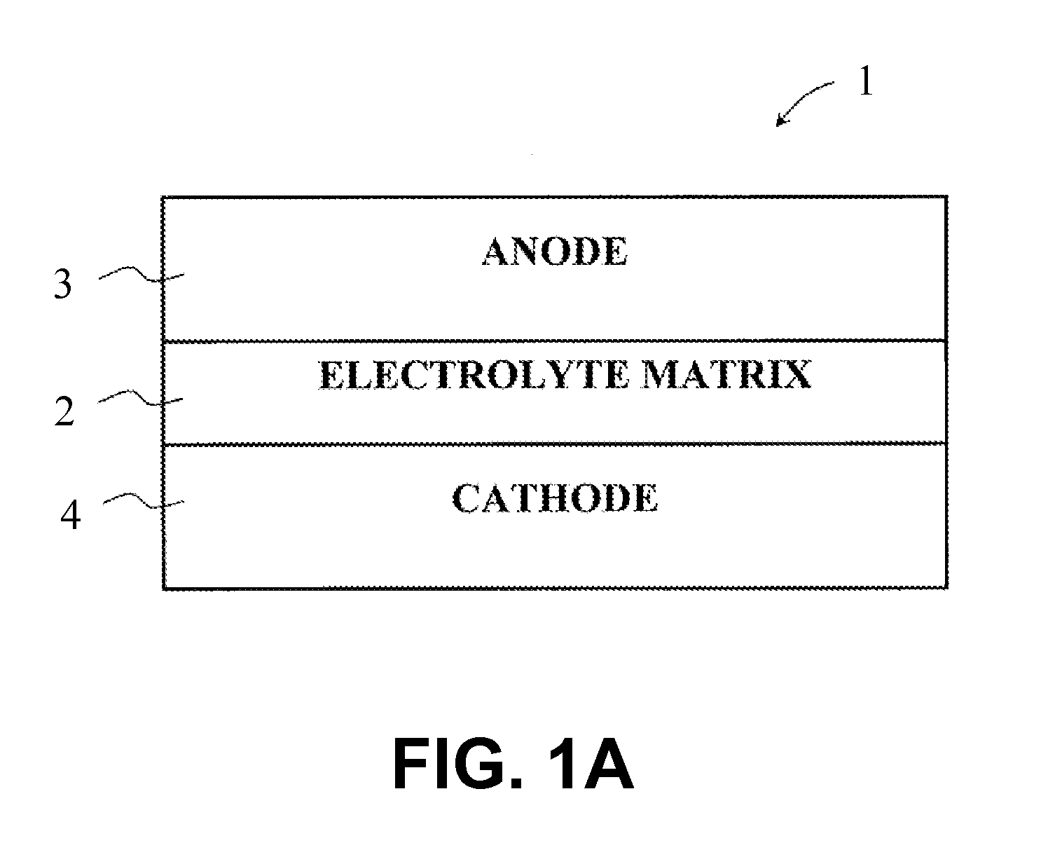
[0017]FIG. 1A shows schematic of a fuel cell 1. The fuel cell 1 comprises an electrolyte matrix 2, an anode 3, and a cathode 4. The anode 3 and the cathode 4 are separated from one another by the matrix 2. Flue gas from a combustion exhaust supply unit is fed to the cathode 4 as oxidant gas. In the fuel cell 1, fuel gas and oxidant gas undergo an electrochemical reaction in the presence of a carbonate electrolyte present in the pores of the electrolyte matrix 2. In the illustrative system disclosed below, the fuel cell 1 comprises a fuel cell stack assembly in which multiple individual fuel cells 1 are stacked and connected in series.

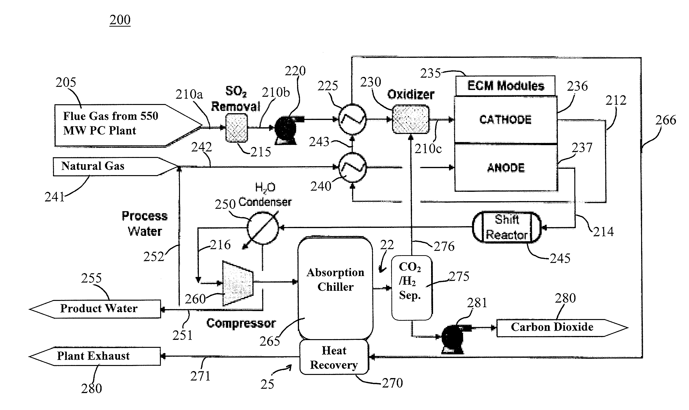
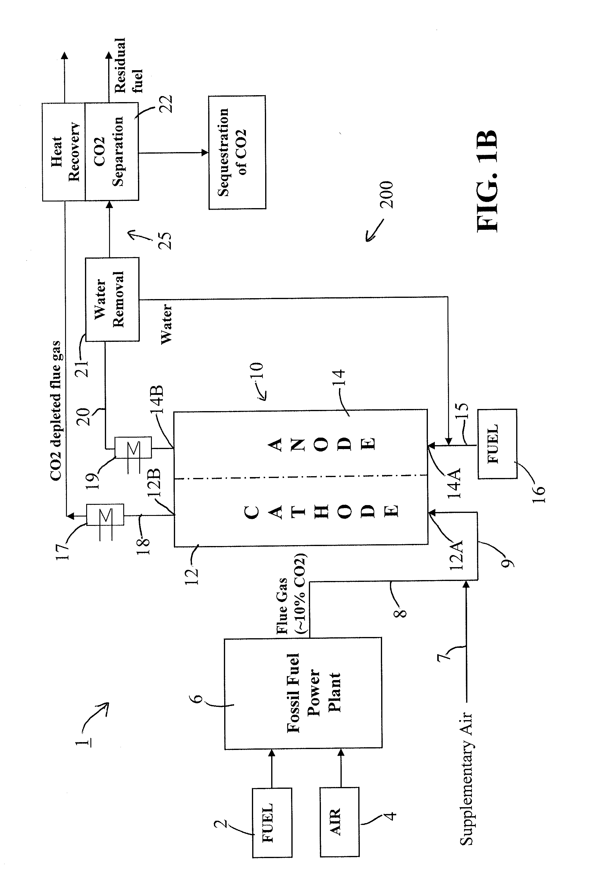
[0018]FIG. 1B shows an integrated power production system 1 comprised of a flue gas generating assembly 6, which includes one or more of a fossil fueled installation, facility or device, a boiler, a combustor, a furnace and kiln in a cement factory (hereinafter “fossil fueled installation, facility or device”), and a power producing gas separation and c...


PUM

PropertyMeasurementUnit
pressureaaaaaaaaaa
temperatureaaaaaaaaaa

Abstract

A power producing system adapted to be integrated with a flue gas generating assembly, the flue gas generating assembly including one or more of a fossil fueled installation, a fossil fueled facility, a fossil fueled device, a fossil fueled power plant, a boiler, a combustor, a furnace and a kiln in a cement factory, and the power producing system utilizing flue gas containing carbon dioxide and oxygen output by the flue gas generating assembly and comprising: a fuel cell comprising an anode section and a cathode section, wherein inlet oxidant gas to the cathode section of the fuel cell contains the flue gas output from the flue gas generating assembly; and a gas separation assembly receiving anode exhaust output from the anode section of the fuel cell and including a chiller assembly for cooling the anode exhaust to a predetermined temperature so as to liquefy carbon dioxide in the anode exhaust, wherein waste heat produced by the fuel cell is utilized to drive the chiller assembly.

Description

BACKGROUND OF THE INVENTION[0001]This invention relates to fuel cell power production systems and, in particular, to a fuel cell power producing gas separation system and method.[0002]A fuel cell is a device which directly converts chemical energy stored in a fuel into electrical energy through electrochemical reactions. Generally, a fuel cell comprises an anode and a cathode separated by an electrolyte, which serves to conduct electrically charged ions. Molten Carbonate Fuel Cells (MCFCs) operate by passing a reactant fuel gas through the anode, while oxidizing gas, such as carbon dioxide and oxygen, is passed through the cathode.[0003]Combustion-based power plants produce energy by combusting flammable hydrocarbon based fuels including coal, natural gas, biogas, and syngas. As a result of the combustion process, combustion-based power plants generate flue gas, which is often disposed of by atmospheric emissions. Such emissions, however, are harmful to the environment because they ...

Claims


Application Information

Patent Timeline
Patent Type & Authority Applications(United States)
IPC IPC(8): H01M8/06H01M8/14
CPCH01M8/0668H01M2008/147H01M8/0631H01M8/145H01M8/04014H01M2250/40Y02P90/40H01M8/0675H01M8/04022H01M8/04089H01M8/04164Y02E60/50
Inventor GHEZEL-AYAGH, HOSSEIN
Owner FUELCELL ENERGY INC
Why Eureka
Try Eureka