Tarp and ballast system

Active Publication Date: 2012-12-20
JMW WELDING & MFG
View PDF3 Cites 4 Cited by
  • Summary
  • Abstract
  • Description
  • Claims
  • Application Information

AI Technical Summary

Benefits of technology

[0008]The present invention in one preferred embodiment is drawn to a large industrial tarp for use as a temporary landfill cover, constructed of a plurality of panels that are connected via seams oriented along the length of the tarp. The improved tarp has lengthwise ballast pockets, or chain pockets, at both sides of the tarp extending the length thereof. Both of the chain pockets have an elongated ballast, or length of chain fixed therein. The improved tarp also has a plurality of widthwise ballast pockets, or cable pockets, oriented in a direction transverse to the panel seams. The tarp also includes various reinforcement straps attached thereto.

Problems solved by technology

However, repeatedly covering the working face with soil requires a significant amount of time, and the soil occupies valuable space in the landfill.
However, if the ends of the cable fray, they can damage the tarp and allow the cable to be dislodged from the sleeve.
In addition, it can be difficult to withdraw and insert a cable that has frayed ends.
Furthermore, it is tedious and time consuming to seal both ends of each sleeve after insertion and unseal one end of each sleeve prior to withdrawal of the cables.
In addition, if the tarp is being deployed and removed with an Automatic Tarpin

Method used


Image

  • Tarp and ballast system
  • Tarp and ballast system
  • Tarp and ballast system

Examples


Example

[0017]Reference will now be made in detail to the present preferred embodiment of the invention, examples of which are illustrated in the accompanying drawings.

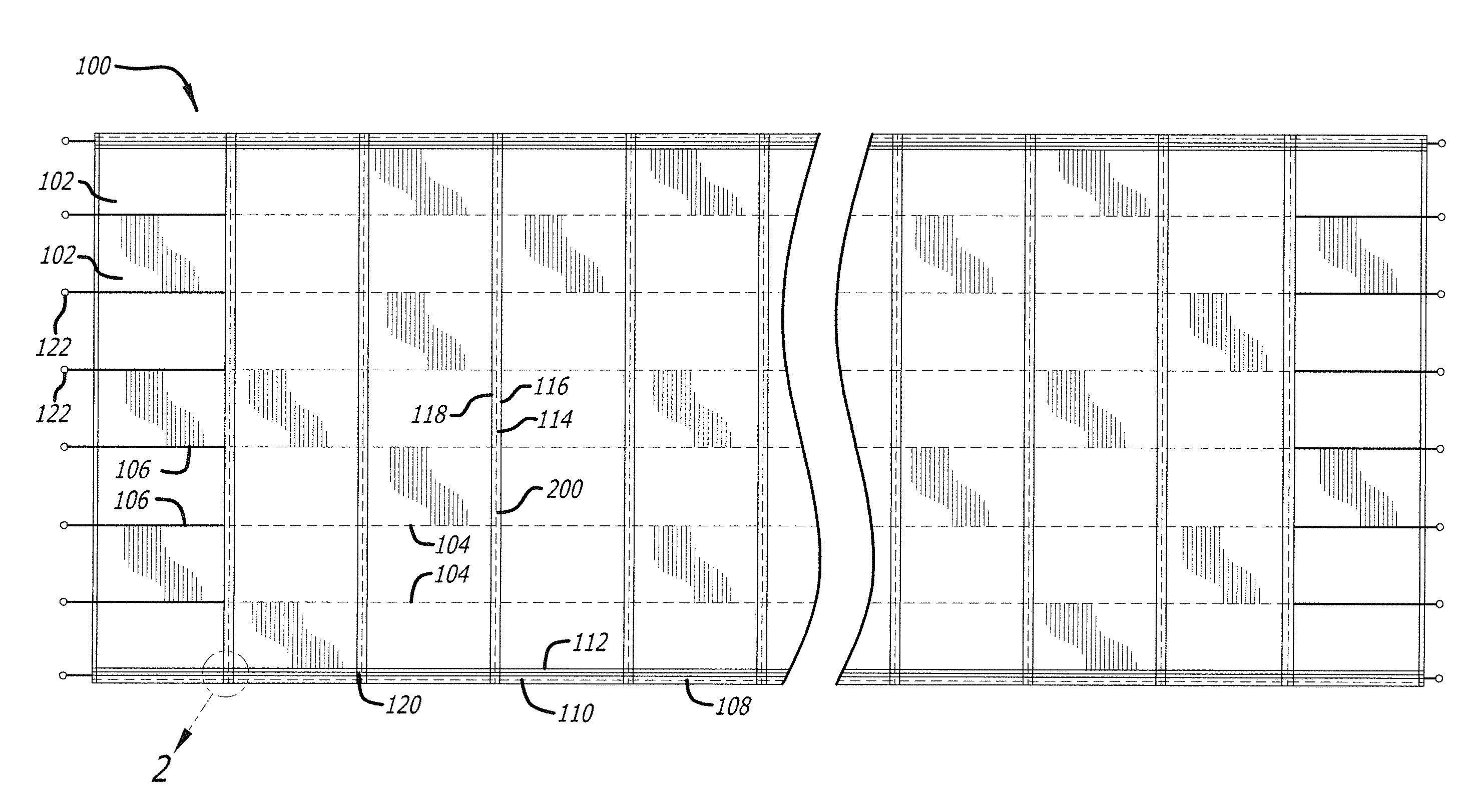
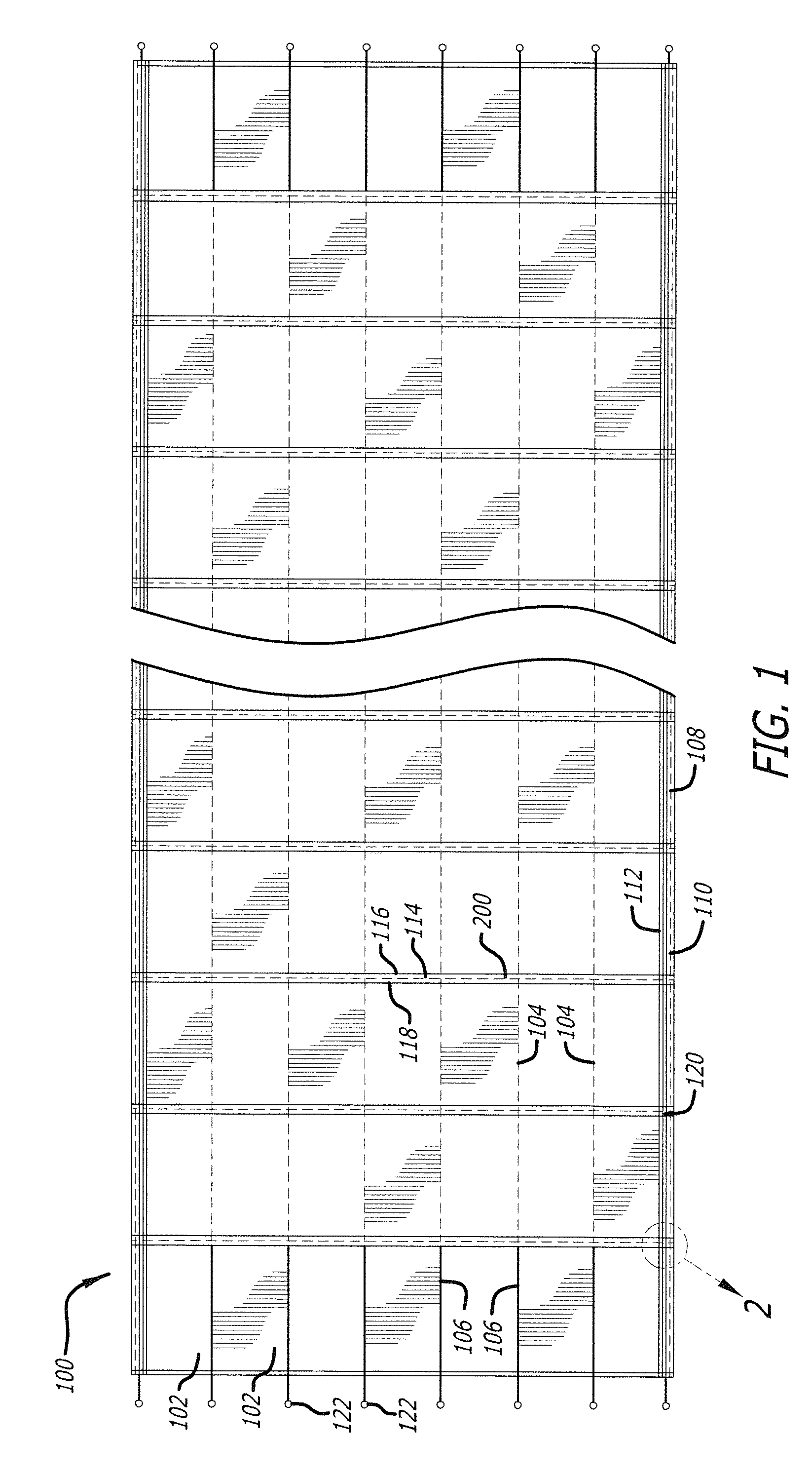
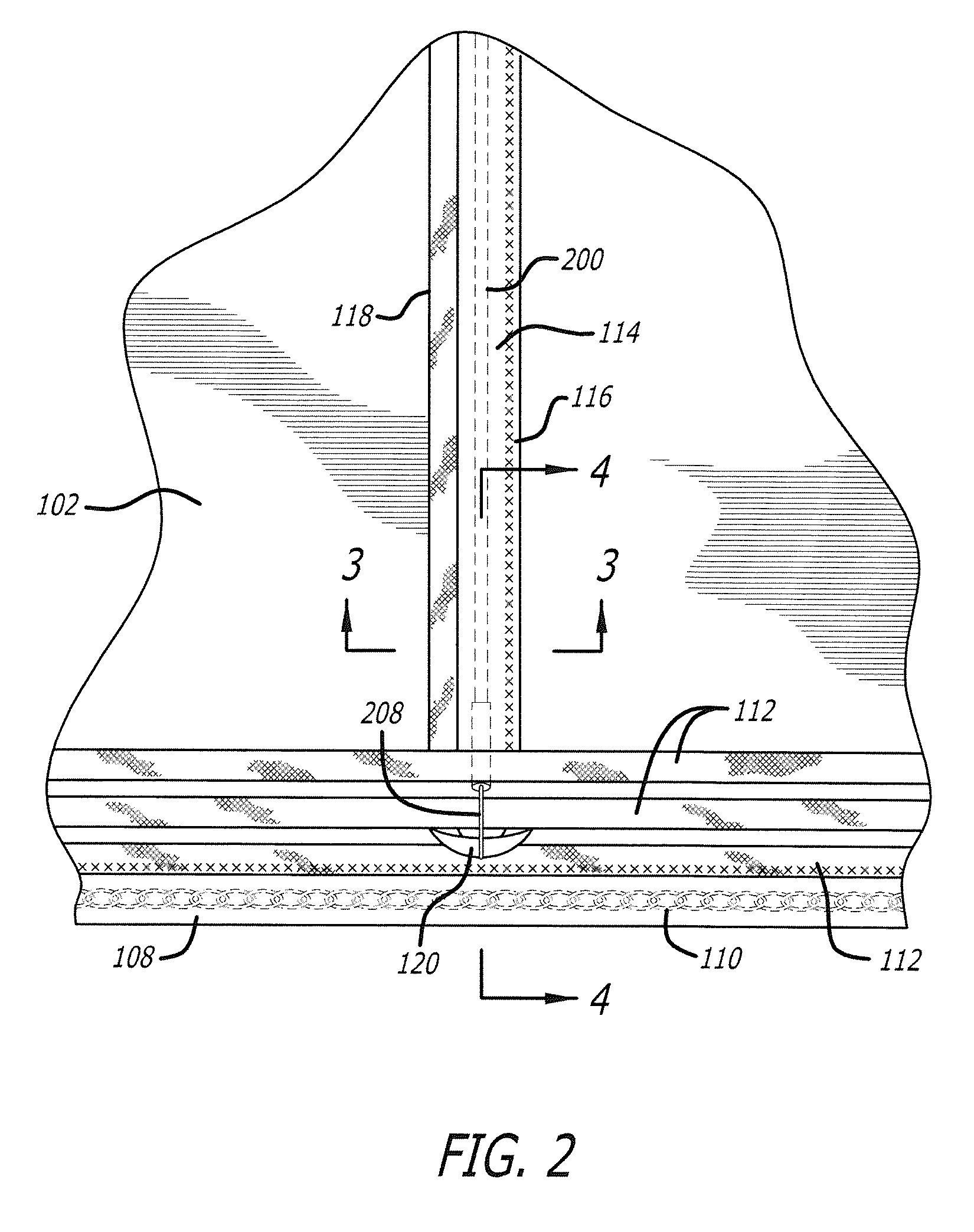
[0018]FIGS. 1 to 6 show a preferred embodiment of a tarp 100. In this preferred embodiment, tarp 100 is primarily configured to be used as a temporary cover for the working face of a landfill. Furthermore, tarp 100 is preferably configured to be used in conjunction with an Automatic Tarping Machine, such as the one disclosed in U.S. Pat. No. 5,304,014 to John D. Slutz. The preferred elements of tarp 100 and their interrelationship are described below.

[0019]Referring to FIG. 1, tarp 100 is constructed from a plurality of panels 102. Panels 102 are preferably sewn together along the lengths thereof, thereby creating panel seams 104 that run along the length of tarp 100. The lengths of panels 102 are approximately the same length as the overall length of tarp 100. Panels 102 may be attached to one another in other ways without d...


PUM


Abstract

An improved tarp and ballast system that includes a plurality of panels attached to one another along the lengths thereof, wherein the lengths of the panels correspond to the length of the tarp. The tarp also includes chain pockets located at the sides of the tarp which run the length of the tarp and have chains secured therein. The tarp further includes a plurality of cable pockets and associated ballast anchors oriented across the width of the tarp which are adapted to secure a plurality of ballast cables to the tarp.

Description

BACKGROUND OF THE INVENTION[0001]The present application claims the benefit of U.S. Provisional Application No. 61 / 497,634, filed Jun. 16, 2011; which is incorporated by reference herein.FIELD OF THE INVENTION[0002]The present invention relates to improvements in the construction of, and ballast systems for, large industrial tarps, particularly those used in temporarily covering sanitary landfill sites.DESCRIPTION OF THE RELATED ART[0003]While the present invention is directed to improvements in the construction of, and ballast systems for, large industrial tarps generally, it is particularly well suited for use as a temporary landfill cover. Landfill operators are required to cover the working face of the landfill when the site is not being worked. That is, the working face must be covered to prevent debris from blowing away, minimize odor, and minimize access by pests and rodents. Traditionally, the working face is covered with a layer of soil. However, repeatedly covering the wor...

Claims


Application Information

Patent Timeline
IPC IPC(8): B32B3/06B23P11/00
CPCB09B1/004Y10T29/49826Y10T428/24008Y02W30/30
Inventor SLUTZ, MICHAEL W.
Owner JMW WELDING & MFG
Why Eureka
Try Eureka