Syringe Evacuator

Inactive Publication Date: 2012-12-27
MEDINVENTION
View PDF2 Cites 5 Cited by
  • Summary
  • Abstract
  • Description
  • Claims
  • Application Information

AI Technical Summary

Benefits of technology

[0005]These and other problems are generally solved or circumvented, and technical advantages are generally achieved, by advantageous embodiments of the present invention, including a syringe evacuator configured to discharge a syringe at a controllable rate

Problems solved by technology

Motors and pneumatic drives have the potential for delivering a consistent force, but have the disadvantage of increased complexity, expense, and the need for an

Method used


Image

  • Syringe Evacuator
  • Syringe Evacuator
  • Syringe Evacuator

Examples


Embodiment Construction

[0016]The making and using of the present exemplary embodiments are discussed in detail below. It should be appreciated, however, that the present invention provides many applicable inventive concepts that can be embodied in a wide variety of specific contexts. The specific embodiments discussed are merely illustrative of specific ways to make and use the invention, and do not limit the scope of the invention.

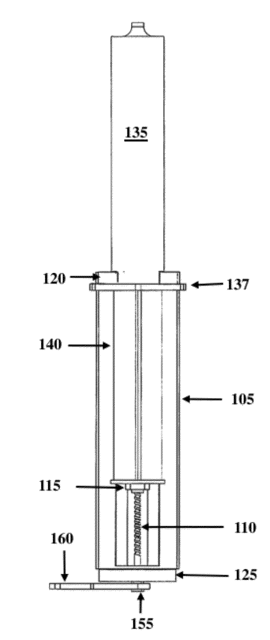
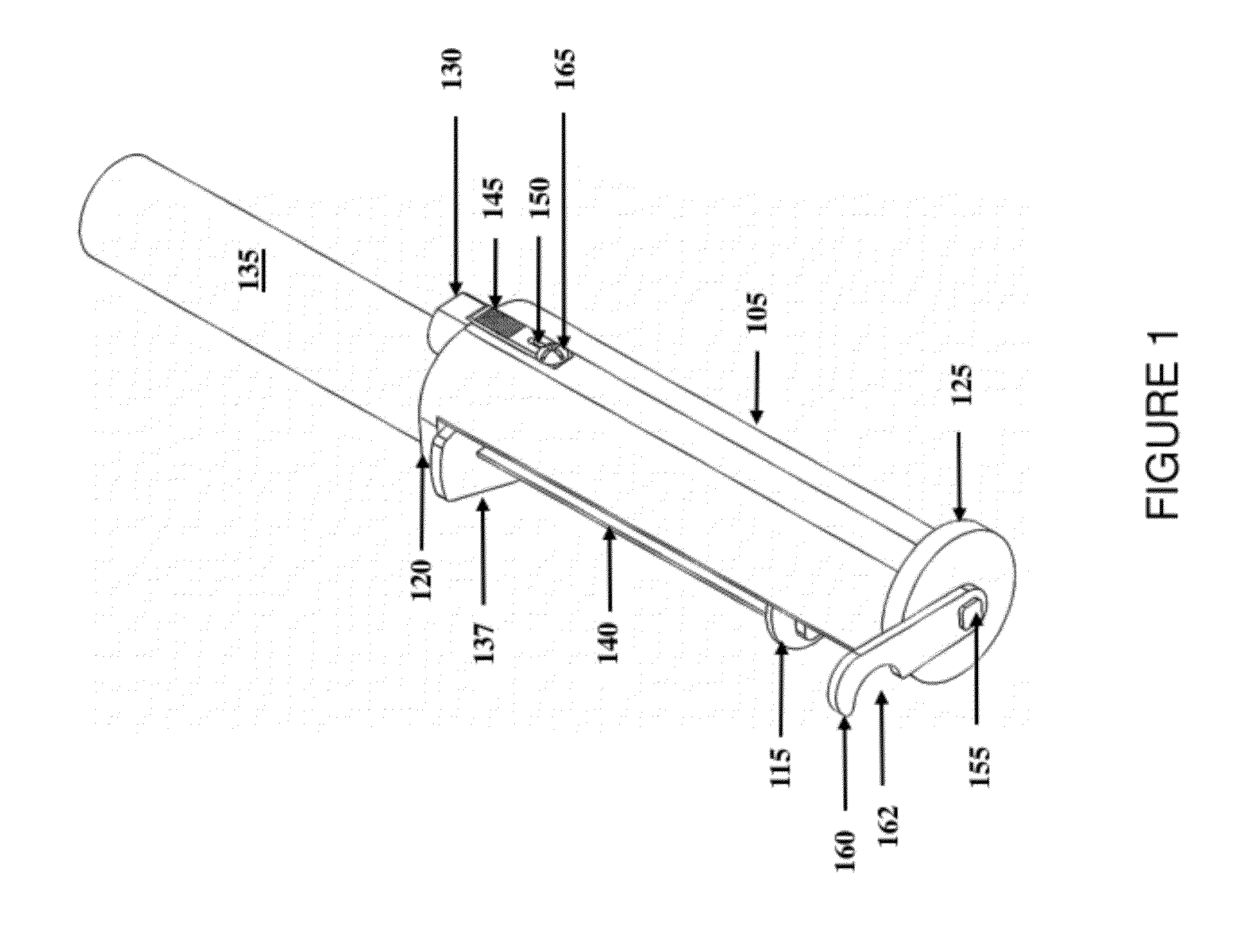
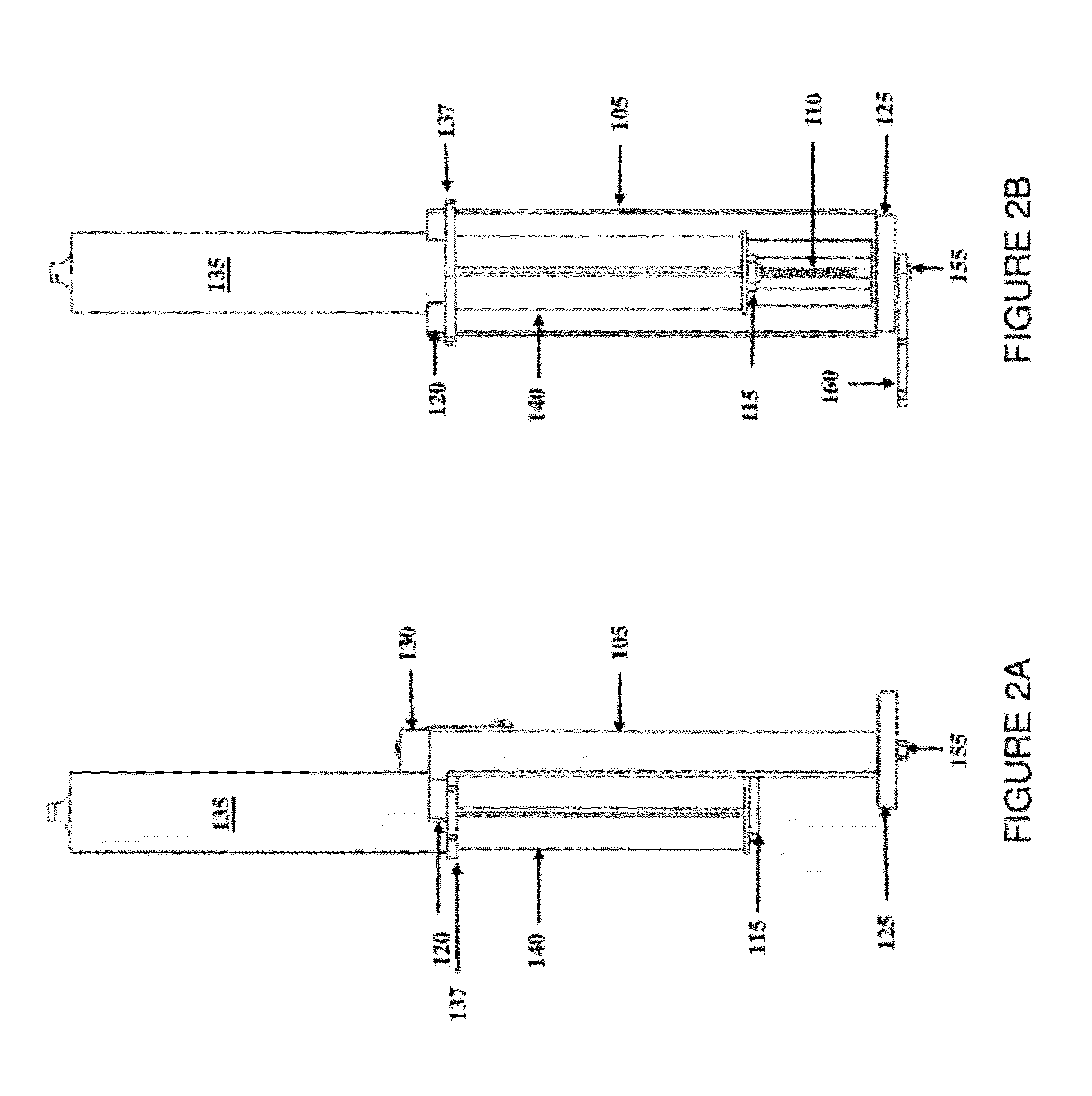
[0017]The present invention will be described with respect to exemplary embodiments in a specific context, namely, a syringe evacuator that produces a substantially consistent and controllable rate of evacuation (or discharge) of the contents of a syringe and methods of forming and operating the same. While the principles of the present invention will be described in the environment of a medical procedure, any application that may benefit from a syringe evacuator is well within the broad scope of the present invention.

[0018]There are numerous applications in medicine such as di...


PUM


Abstract

A syringe evacuator configured to discharge a syringe at a controllable rate. In one embodiment, the syringe evacuator includes a threaded shaft and a syringe depressor platform threaded onto the threaded shaft. The syringe evacuator also includes a spiral spring coupled to the threaded shaft configured to rotate the threaded shaft.

Description

TECHNICAL FIELD[0001]The present invention is directed, in general, to a syringe evacuator that produces a consistent and controllable rate of evacuation of the contents of a syringe.BACKGROUND[0002]In the medical field, there is a need to evacuate syringes at a controlled rate. Various techniques have been proposed to perform this function including motorized pumps, pneumatic drives and coil springs. Motors and pneumatic drives have the potential for delivering a consistent force, but have the disadvantage of increased complexity, expense, and the need for an electrical or compressed air power source. Coil springs have been used to depress syringe plungers, but exert significantly different forces when fully compressed and minimally compressed. There are numerous extant spring-driven syringe devices, but such devices lack the ability to give a steady flow rate. The current technology has predictably varying flow depending on the compression of a spring.[0003]A reusable and adjustab...

Claims


Application Information

Patent Timeline
IPC IPC(8): A61M5/315
CPCA61M2005/2026A61M5/20
Inventor RUDE, MALCOLMMIRTH, BRIAN ADLER
Owner MEDINVENTION
Why Eureka
Try Eureka