
Femoral component instrument

a technology of femoral components and instruments, applied in the field of femoral components instruments, can solve the problems of inability to use the inserter as an impactor, inability to achieve the effect of reducing the risk of injury, and reducing the safety of patients

Active Publication Date: 2013-01-17
ZIMMER INC
View PDF7 Cites 22 Cited by
  • Summary
  • Abstract
  • Description
  • Claims
  • Application Information

AI Technical Summary

Benefits of technology

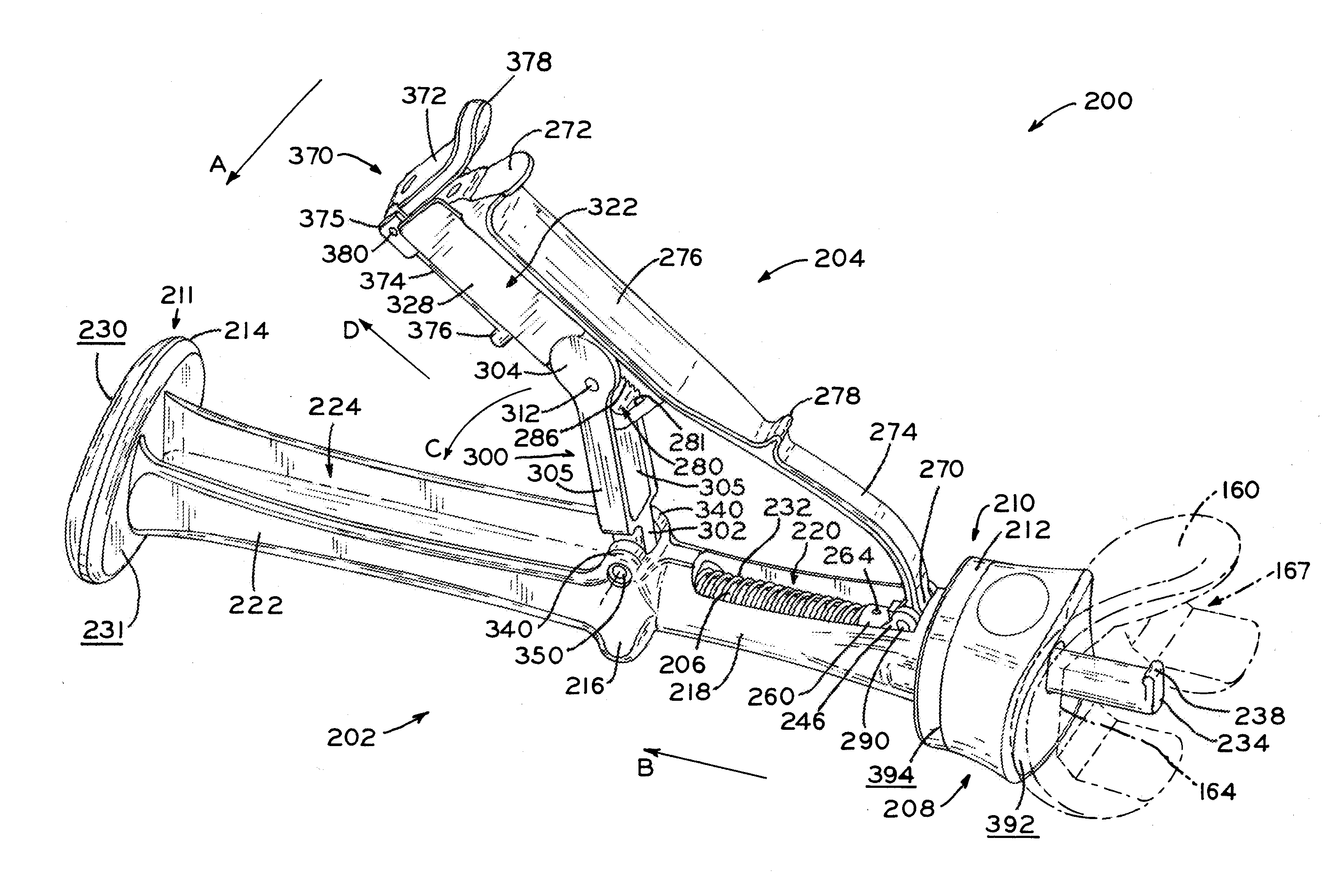
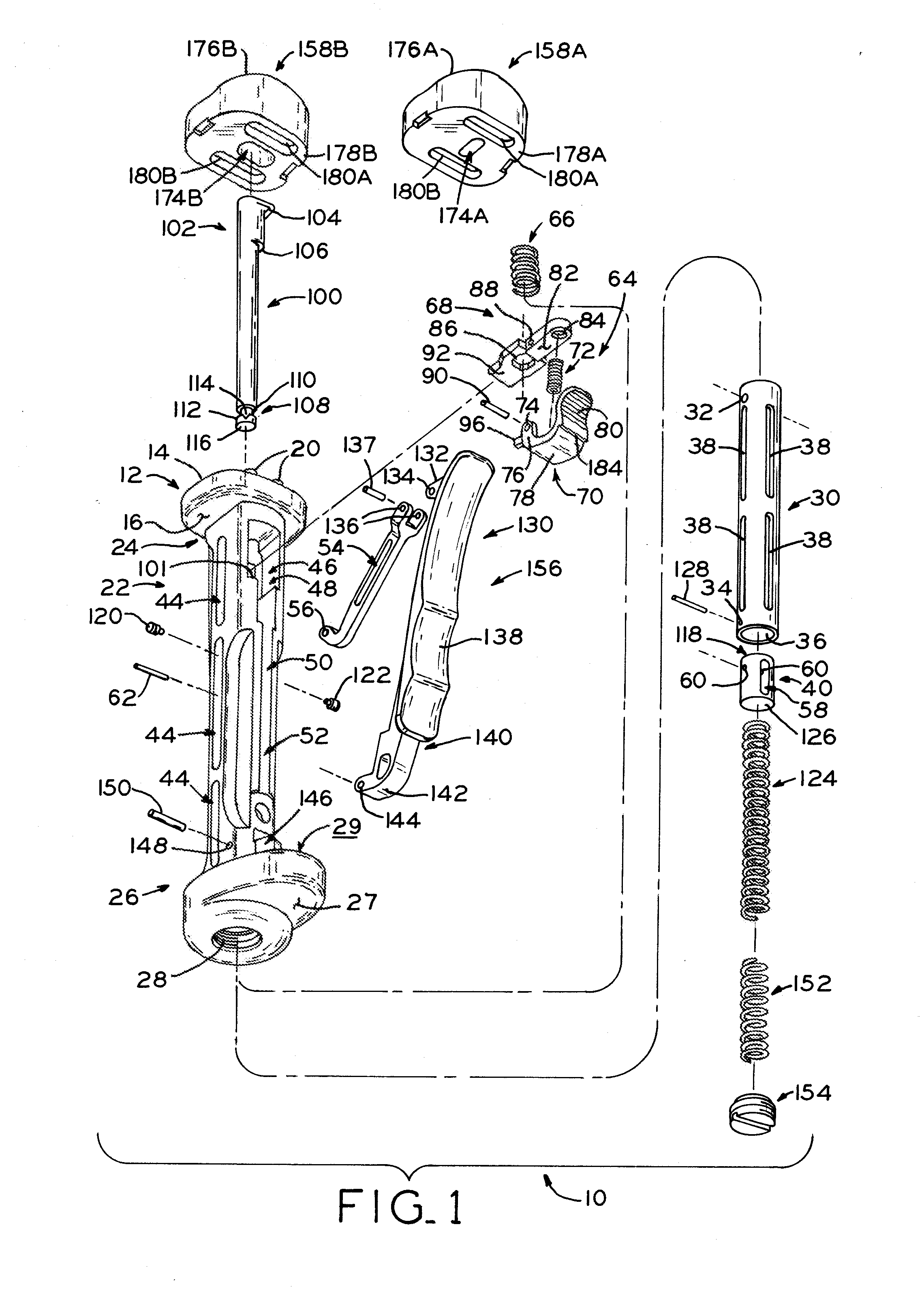
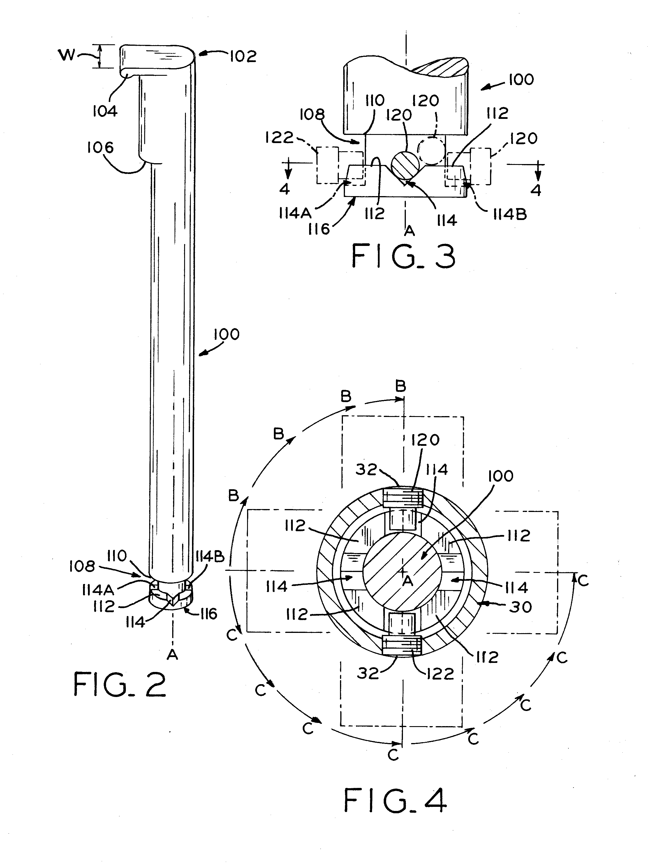
The present disclosure provides a femoral component inserter with a securement mechanism that allows for different securement locations for PS and CR femoral components. The inserter includes a modular pad that can be chosen for the specific type of femoral component. The inserter also has a locking feature that can be used as an impactor without interfering with the femoral component. The locking mechanism includes a rotatable post with a locking lip that can be adjusted to accommodate the different features on the bone contacting surfaces of the femoral components. The post / locking lip combination can supply a force in a direction that is substantially equidistant to each contact point on a particular line. The inserter can act as an impactor when the femoral component is not locked to the pad.

Problems solved by technology

A knee may incur wear, significant disease, or trauma that warrants replacement of the knee with a prosthetic knee implant including prosthetic components such as a femoral component to replace the distal end of the femur, a tibial component to replace the proximal end of the tibia, and a bearing insert to replace articulating tissue between the femur and the tibia.
A trial reduction of the knee joint with the provisional components in place may indicate that the preliminary size determination was not ideal.
As securement mechanisms of inserters tend to secure to a bone contacting surface of a prosthesis, utilizing the inserter as an impactor is generally not possible.

Method used


Image

  • Femoral component instrument
  • Femoral component instrument
  • Femoral component instrument

Examples


Embodiment Construction

[0041]The present disclosure uses anatomic points of reference to describe the instrument herein. For example, the terms proximal and distal are used with reference to a distal femoral bone that the instrument is to be positioned against (the proximal end of the instrument being the end that, when the instrument is in use, is closest to the distal femoral bone while the distal end of the instrument is the end that is farthest from the distal femoral bone).

[0042]Disclosed is an inserter for interchangeable use with PS and CR femoral components. The inserter includes a rotatable post having a locking lip extending transversely from the post at a locking end for interchangeable engagement with either PS or CR femoral components. In an unlocked position, the lip, via rotation of the post, may rotate to a selected position.

[0043]The locking end of the post keys to a pad aperture such that rotation of the pad dictates a corresponding rotation of the post to one of two securement positions...


PUM


Abstract

A femoral component instrument includes a rotatable locking mechanism such as a post and is capable of interchangeable use between posterior stabilizing (“PS”) and cruciate retaining (“CR”) femoral component types via the locking mechanism. The instrument further includes a modular pad so that a pad specific to the prosthesis type may be chosen. Each pad of a particular femoral component type is useable with a variety of sizes of that femoral component type. The locking mechanism of the instrument is alternatively useable with a variety of femoral component types. The locking end of the post keys to a pad aperture to rotatably align the post to an appropriate securement position. If a femoral component is not locked to the pad, the post of the instrument moves from an exposed position proximal to the proximal pad surface to a retracted position distal to the proximal pad surface, thereby permitting impaction.

Description

BACKGROUND[0001]1. Field of Disclosure[0002]The present disclosure relates to instruments used in orthopedic surgery, and, in particular, to a femoral component instrument, which can be used as an inserter, impactor and extractor for use in the placement, impaction and extraction of a femoral prosthesis or femoral provisional component, for example.[0003]2. Description of Related Art[0004]The knee is the joint between the femur and the tibia. The knee joint is formed of a pair of condyles located at a distal portion of the femur, a tibial plateau located at a proximal end of the tibia and shaped to mate with the pair of condyles, and a pair of menisci positioned between the tibial plateau and the condyles. A knee may incur wear, significant disease, or trauma that warrants replacement of the knee with a prosthetic knee implant including prosthetic components such as a femoral component to replace the distal end of the femur, a tibial component to replace the proximal end of the tibi...

Claims


Application Information

Patent Timeline
IPC IPC(8): A61B17/56A61F2/38
CPCA61F2/3859A61F2/4603A61F2002/4628A61F2002/4622A61F2002/4627A61F2/461A61B17/92A61F2/4607
Inventor JONES, NOLAN C.VANDIEPENBOS, JEFFERY A.
Owner ZIMMER INC
Learn More