Multi-Function Rear Seat Structure Mechansim

a rear seat and multi-functional technology, applied in the direction of movable seats, vehicle components, vehicle arrangements, etc., can solve the problem of reducing the amount of storage space available behind the rear seat assembly row

Active Publication Date: 2013-02-28
MAGNA SEATING
View PDF3 Cites 32 Cited by
  • Summary
  • Abstract
  • Description
  • Claims
  • Application Information

AI Technical Summary

Problems solved by technology

However, positioning the rear seat assemblies in the forward position decreases the amount of storage space available behind the row of front seat assemblies.

Method used


Image

  • Multi-Function Rear Seat Structure Mechansim
  • Multi-Function Rear Seat Structure Mechansim
  • Multi-Function Rear Seat Structure Mechansim

Examples


Embodiment Construction

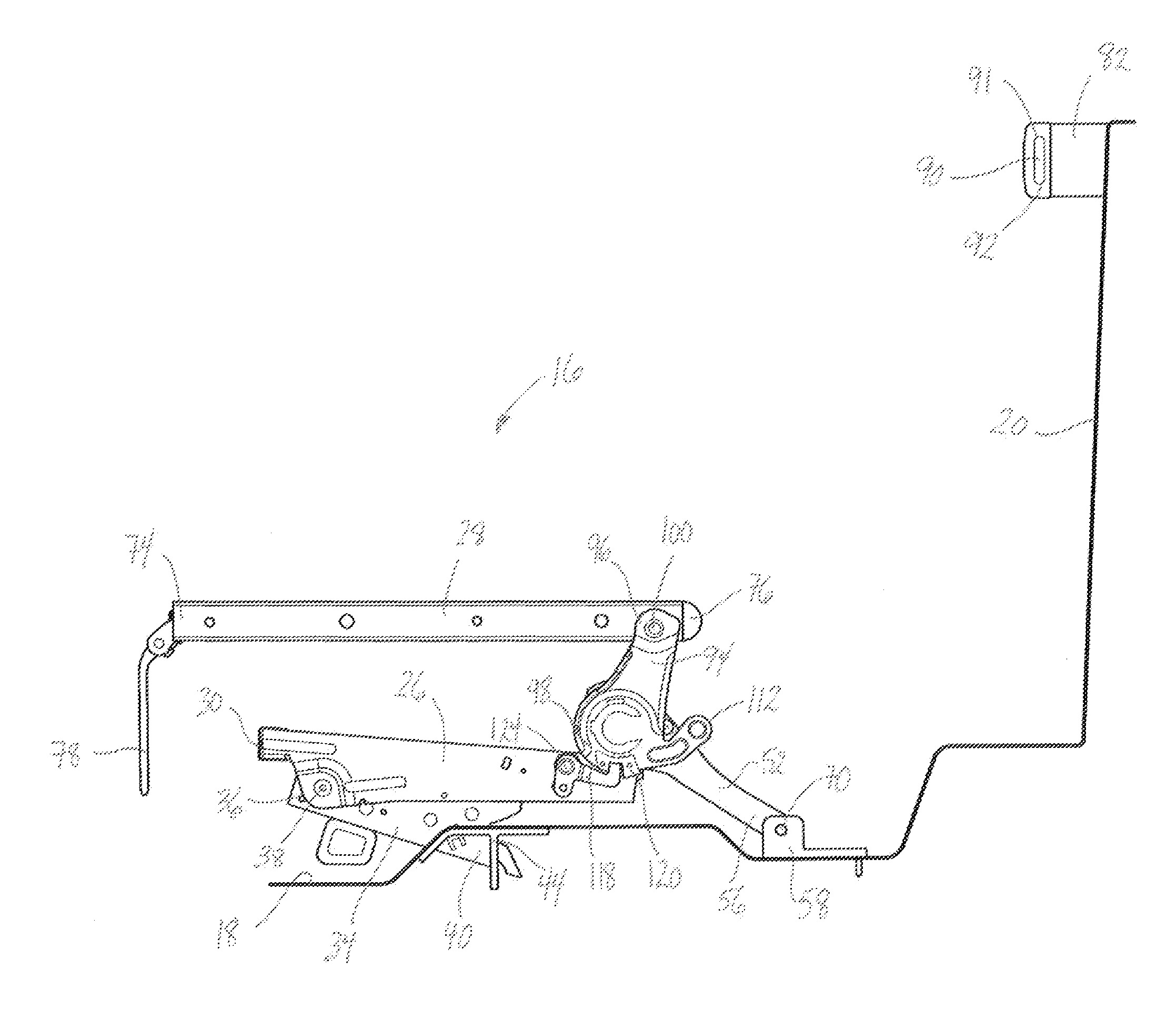
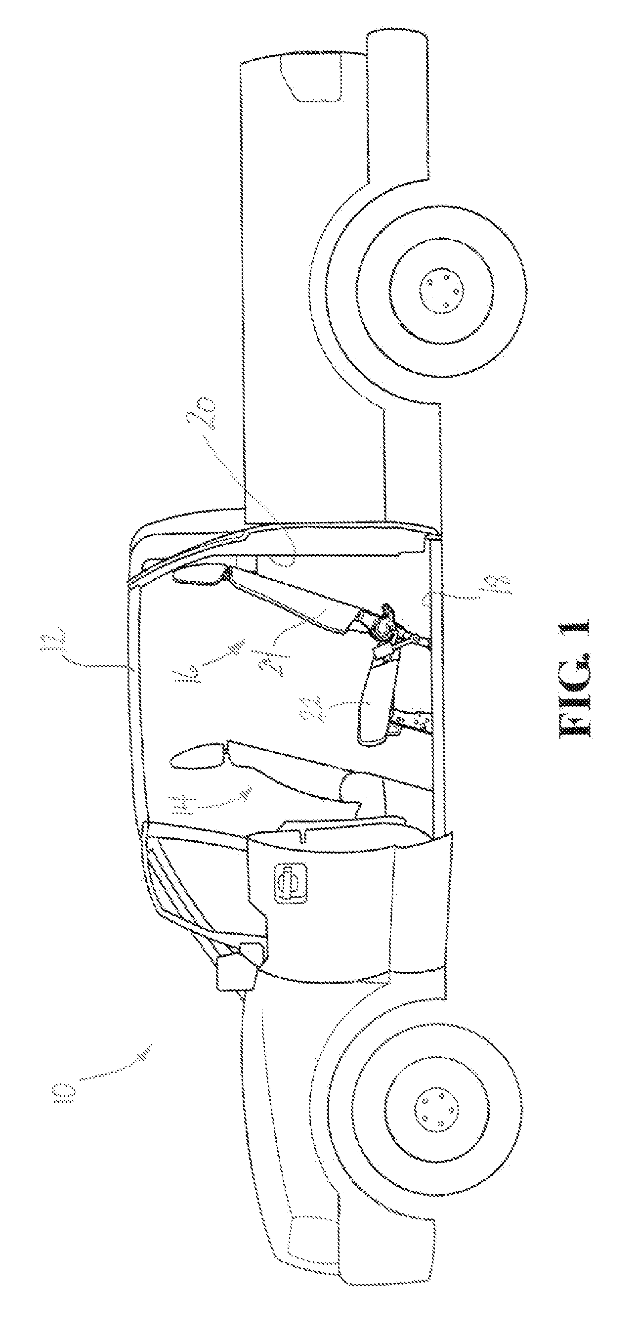
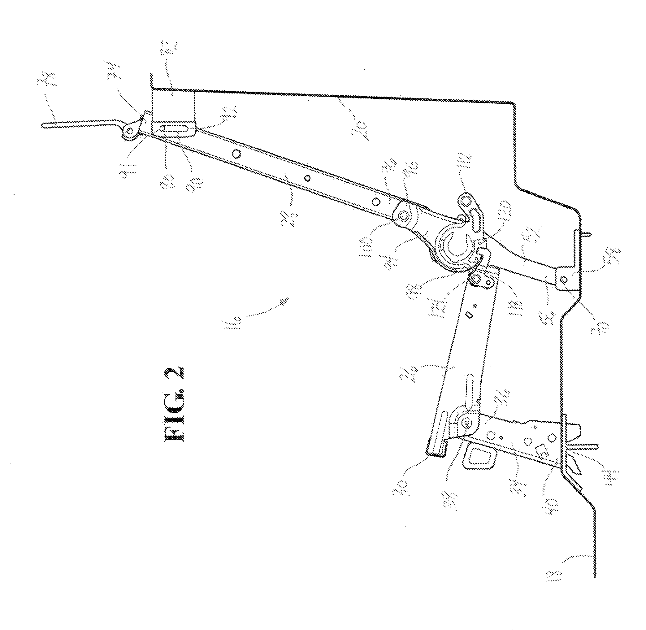
[0023]Referring to the Figures, a pick-up truck 10 includes a passenger cabin 12 having a front seat assembly, generally shown at 14, and a rear seat assembly, generally shown at 16. Both the front seat assembly 14 and the rear seat assembly 16 are mounted on a floor 18 of the passenger cabin 12 and the rear seat assembly 16 is positioned adjacent a back wall 20 of the passenger cabin 12. While the rear seat assembly 16 is shown in the pick-up truck 10, it is appreciated that the rear seat assembly 16 may be used in a rear portion of any vehicle where space is at a premium and occupant comfort is desired.

[0024]The rear seat assembly 16, or seat assembly, as referred to herein, includes a seat cushion 22 and a seat back 24. As is well known in the art, the seat cushion 22 includes a foam pad covered in upholstery and supported by a seat cushion frame 26. Similarly, the seat back 24 includes a foam pad covered in upholstery and supported by a seat back frame 28. The seat cushion 22 an...


PUM


Abstract

A seat assembly includes a seat cushion and seat back supported above a floor by a rear leg. The seat back is pivotally coupled to a recliner bracket. The seat cushion is selectively pivotally locked relative to the recliner bracket. A disc recliner operatively couples the recliner bracket and rear leg. The disc recliner allows the rear leg to pivot relative to the recliner bracket to move the seat assembly from a-design seating position to a slouch position. The seat back is pivoted towards the seat cushion and the recliner allows the rear leg to pivot relative to the recliner bracket, thereby lowering the seat, assembly to move the seat assembly to a fold and kneel position. The seat cushion is unlocked relative to the recliner bracket to pivot the seat cushion towards the seat back to move the seat assembly to a stadium position.

Description

CROSS-REFERENCE TO RELATED APPLICATION[0001]This application claims priority to and ail the benefits of U.S. Provisional Application Ser. No. 61 / 528,835, filed Aug. 30, 2011.BACKGROUND OF THE INVENTION[0002]1. Field of the Invention[0003]The present invention relates to a seat assembly for an automotive vehicle. More particularly, the present invention relates to a rear seat assembly for a pick-up truck that is selectively movable between a design seating position, a plurality of slouch positions, a fold and kneel position, and a stadium position.[0004]2. Description of Related Art[0005]It is common for pick-up trucks to haw passenger cabins with one or more rear seal assemblies. The rear seat assemblies are positioned between a row of front seat assemblies and a rear wall of the cabin. In order to provide satisfactory passenger comfort for occupants using the rear seat assemblies, the rear seat assemblies may be positioned in a forward position relative to the rear wall of the cabi...

Claims


Application Information

Patent Timeline
Patent Type & Authority Applications(United States)
IPC IPC(8): B60N2/22B60N2/20
CPCB60N2/206B60N2/2209B60N2/24B60N2/36B60N2/3047B60N2/3065B60N2/3011
Inventor RUNDE, DAVID M.ZEIMIS, III, PETER PAUL
Owner MAGNA SEATING
Why Eureka
Try Eureka