Electric vehicle

Active Publication Date: 2013-03-28
TOYOTA JIDOSHA KK
View PDF8 Cites 22 Cited by
  • Summary
  • Abstract
  • Description
  • Claims
  • Application Information

AI Technical Summary

Benefits of technology

[0010]Whereas in the related art, the cooling system is stopped in the case where the main switch of the electric vehicle is switched from the on-state to the off-state while the vehicle is traveling, the electric vehicle of the invention does not stop the cooling system in that case. Furthermore in the electric vehicle of the invention, the coolant is actively cooled in preparation for the subsequent switching of the main switch back from the off-state to the on-state. An electric vehicle in accordance with the aspect of the invention includes a main coolant passage that circulates a coolant through a radiator and at least one of an electric motor and an inverter, and a bypass coolant passage that bypasses the electric motor and/or the inverter, wherein if the main switch is switched from the on-state to the off-st

Problems solved by technology

Although the main switch being switched off and on during travel of the vehicle is not a usual manner of use, a driver can erroneously perform such an operation.
However, when the main switch is switched back from the off-state to the on-state while

Method used


Image

  • Electric vehicle
  • Electric vehicle
  • Electric vehicle

Examples


first embodiment

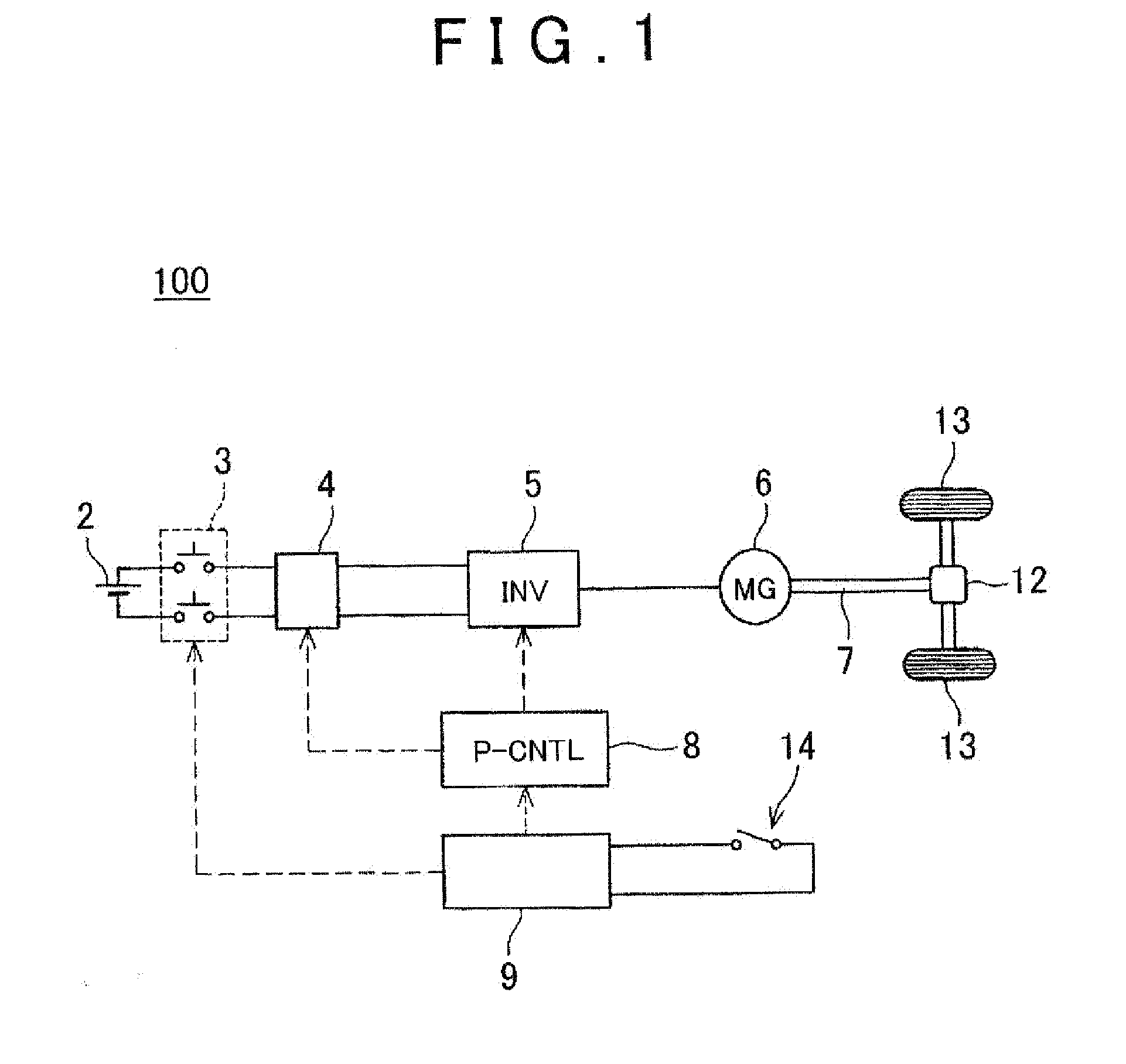
[0019]FIG. 1 shows a block diagram of a drive system of an electric vehicle 100 in accordance with a first embodiment of the invention. The electric vehicle 100 is a one-electric motor electric vehicle that has one electric motor 6 for driving wheels. The electric motor 6 is driven through the use of a battery 2 as an electric power supply. The battery 2 is connected to an inverter 5 via a system main relay 3 and a voltage boost converter 4. The system main relay 3 is a switch for connecting the battery 2 to a drive system (representatively, the inverter 5 and the electric motor 6) of the electric vehicle 100 and disconnecting the battery 2 from the drive system. The system main relay 3 is controlled by a general controller 9 that comprehensively controls the entire electric system of the electric vehicle 100. Typically, the general controller 9 closes the system main relay 3 (connects the battery 2 to the vehicle drive system) when a vehicle main switch 14 provided at a driver's se...

second embodiment

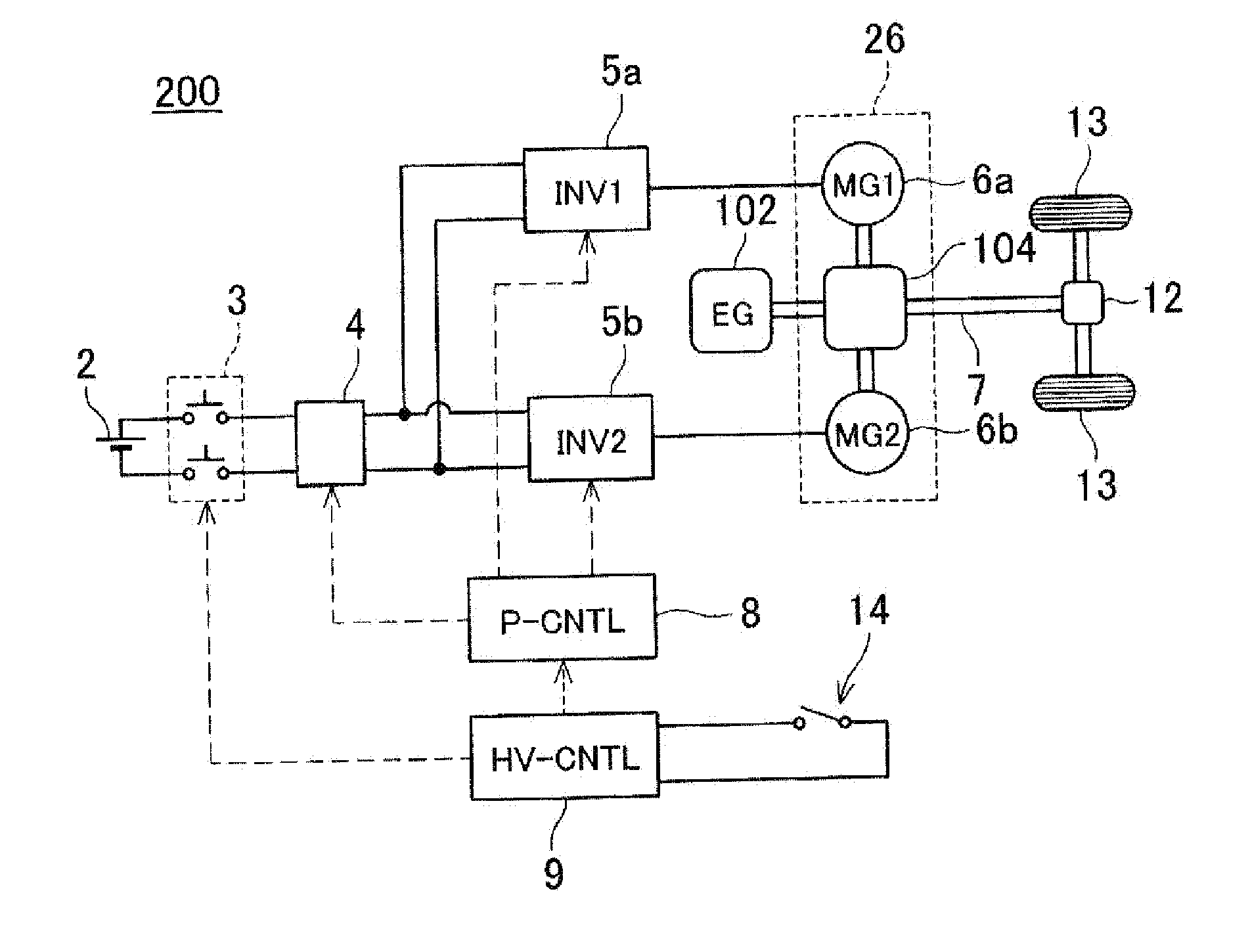
[0032]A second embodiment of the invention will be described. An electric vehicle in accordance with the second embodiment is a hybrid vehicle 200 that has an engine 102 and two electric motors (a first electric motor 6a and a second electric motor 6b) which are provided for the purpose of driving wheels. A block diagram of a drive system of the hybrid vehicle 200 is shown in FIG. 5. The hybrid vehicle 200 includes a first inverter 5a and a second inverter 5b that are provided for the first electric motor 6a (MG1) and the second electric motor 6b (MG2), respectively. Both the inverters 5a and 5b are supplied with electric power from the battery 2. Furthermore, each of the inverters receives a PWM command from an electric motor controller 8. The output torque of the first electric motor 6a, the output torque of the second electric motor 6b and the output torque of the engine 102 are combined or distributed by a power distribution mechanism 104 before being transmitted to an axle shaf...


PUM


Abstract

An electric vehicle includes: an electric motor; an inverter that supplies electric power to the electric motor; and a cooling system that cools at least one of the electric motor and the inverter, the cooling system having: a main coolant passage configured to circulate a coolant through a radiator and at least one of the electric motor and the inverter; a bypass coolant passage, connected to the main coolant passage, that bypasses at least one of the electric motor and the inverter; and a controller configured to switch from the main coolant passage to the bypass coolant passage when a main switch of the vehicle provided at a driver's seat is turned off while the electric vehicle is travelling, and to switch from the bypass coolant passage to the main coolant passage when the main switch is then turned on.

Description

BACKGROUND OF THE INVENTION[0001]1. Field of the Invention[0002]The invention relates to an electric vehicle, such as a pure electric vehicle, a hybrid vehicle or a fuel cell vehicle, that has an electric motor for driving wheels.[0003]2. Description of Related Art[0004]Electric vehicles, unlike common engine vehicles, are equipped with an electric system that handles large current and that includes, for example, an electric motor for driving wheels, a high-capacity and high-voltage battery, an inverter that converts direct-current power from the battery into alternating-current power that is suitable to drive the electric motor, etc. Therefore, the electric vehicles are provided with various safety measures for the electric system and measures against defects in the system, which are not provided for the engine vehicles.[0005]For example, Japanese Patent Application Publication No. 2007-216833 (JP 2007-216833 A) discloses a technology that prevents an event in conjunction with a hy...

Claims


Application Information

Patent Timeline
IPC IPC(8): B60R16/03B60L50/15B60L50/16
CPCB60L1/003Y02T10/7275B60L3/0061B60L11/123B60L11/14B60L11/1881B60L15/2036B60L2210/40B60L2220/42B60L2240/12B60L2240/36B60L2240/421B60L2240/425B60L2240/441B60L2240/525B60L2250/12Y02T10/7241Y02T10/7077Y02T10/7005Y02T90/34Y02T10/6217Y02T10/648B60L3/003B60L50/61B60L50/16B60L58/30Y02T10/62Y02T10/64Y02T10/72Y02T10/7072Y02T90/40Y02T10/70
Inventor HASHIMOTO, HIRONOBU
Owner TOYOTA JIDOSHA KK
Why Eureka
Try Eureka