
Electromagnetically Operated Switching Devices And Methods Of Actuation Thereof

Active Publication Date: 2013-04-11
CAMCON OIL LTD
View PDF6 Cites 2 Cited by
  • Summary
  • Abstract
  • Description
  • Claims
  • Application Information

AI Technical Summary

Benefits of technology

[0018]Preferably, the magnetic flux container also substantially extends over one or both ends of the device, relative to the axis of the coil. This arrangement provides a substantially magnetically sealed device with minimal flux leakage. The shielding effects of the container also serve to avoid the performance of the device being affected by external magnetic fields. In a preferred configuration, components of the device provide a magnetic flux container which substantially encloses the interior of the device to avoid flux leakage.
[0019]The container preferably forms the housing of the device which supports the components within it, providing a compact configuration. This results in a strong, well-protected mechanical construction without requiring an additional housing around the device.
[0020]The armature may comprise flexible material to facilitat

Problems solved by technology

This is likely to be problematic in applications where the device is surrounded by fluid, as there will be a risk of build up of magnetic debris in these regions potentially leading to flow impairm

Method used


Image

  • Electromagnetically Operated Switching Devices And Methods Of Actuation Thereof
  • Electromagnetically Operated Switching Devices And Methods Of Actuation Thereof
  • Electromagnetically Operated Switching Devices And Methods Of Actuation Thereof

Examples


Example

DETAILED DESCRIPTION OF THE DRAWINGS

[0037]It should be noted that the Figures are diagrammatic and not drawn to scale. Relative dimensions and proportions of these Figures have been shown exaggerated or reduced in size, for the sake of clarity and convenience in the drawings. The same reference signs are generally used to refer to corresponding or similar features in modified and different embodiments.

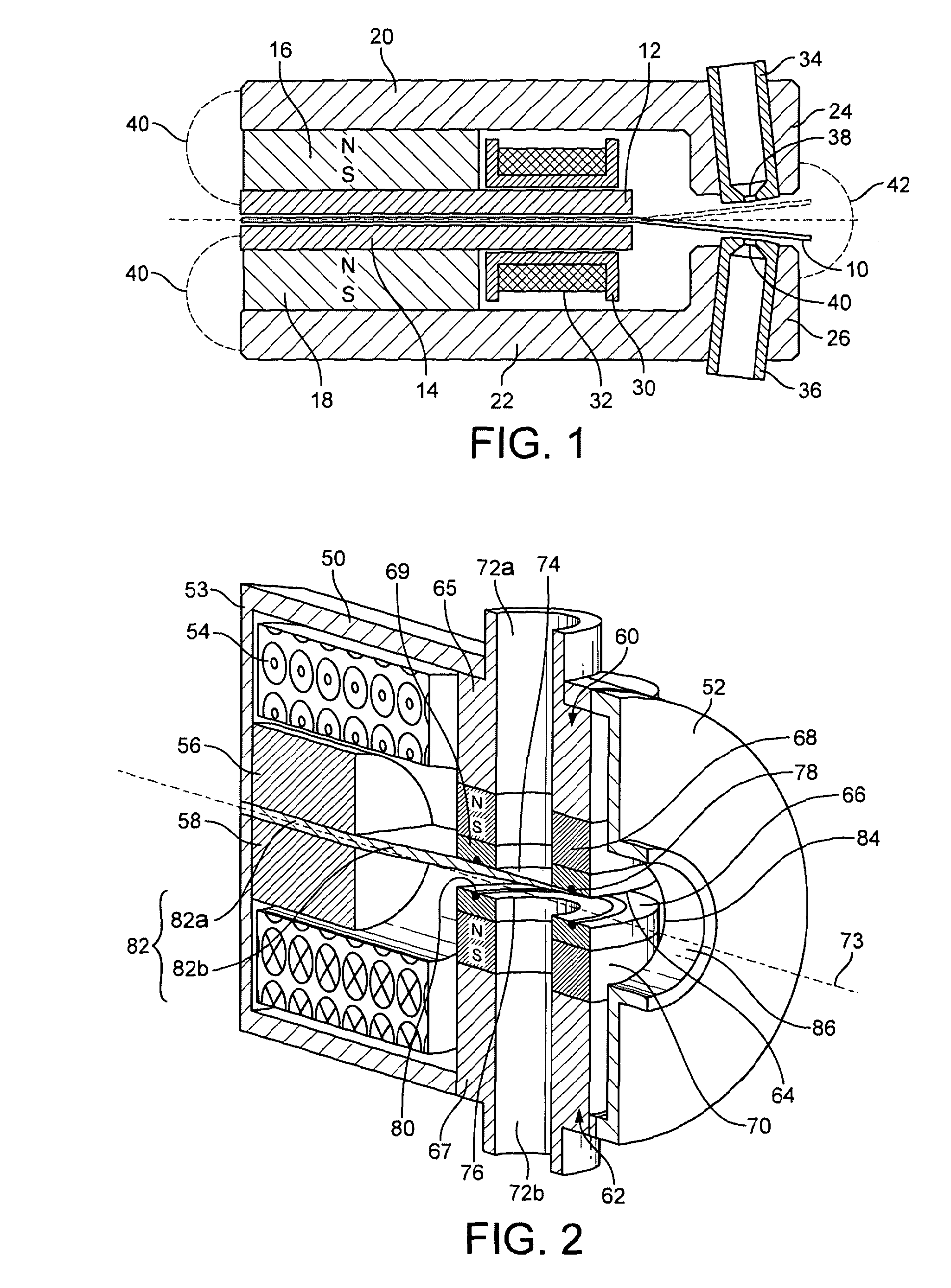
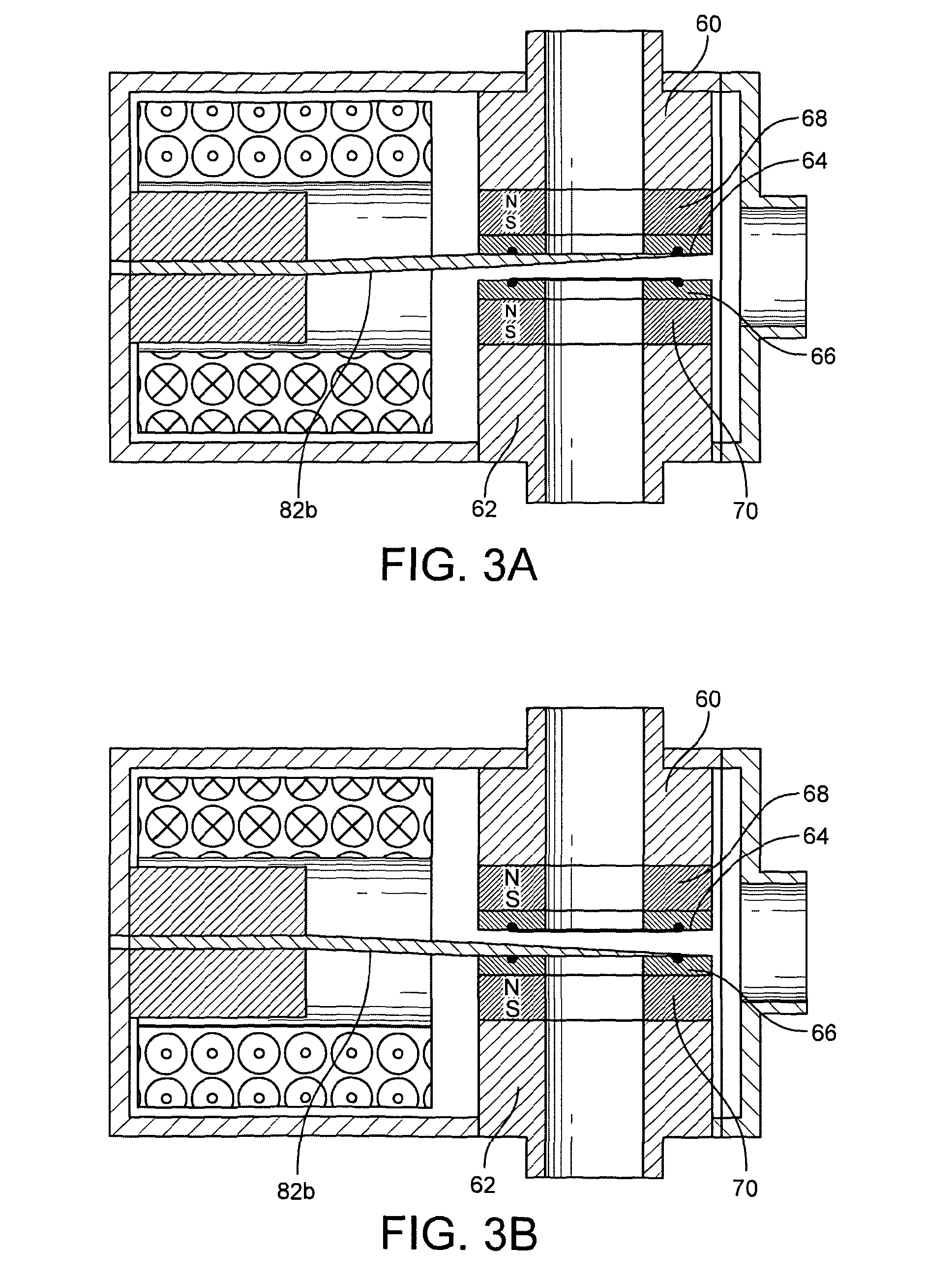
[0038]An electromagnetically operated device embodying the invention is depicted in FIGS. 2, 3A, 3B and 4. The device is housed in a container formed by container body 50 and an end cap 52. The container body is in the form of a hollow cylinder open at one end and having an end portion 53 at the other, with the open end engaged by end cap 52.

[0039]The container body is formed of a material having a high magnetic permeability. It may comprise ferromagnetic material. The end cap may also be formed of a high magnetic permeability material, so that a magnetic flux container is formed by th...


PUM


Abstract

An electromagnetically operated switching device comprises an armature (82,102) having a magnetisable and moveable portion (82b,102b) for displacement between two stable rest positions. Two pole pieces (60,62) are disposed on opposite sides of the armature. The pole pieces form poles of opposing polarity adjacent to the armature, and the armature is magnetically attracted to a respective pole piece in each of its stable rest positions. A coil (54) is arranged to polarise the moveable portion of the armature when the coil is energised, such that the moveable portion of the armature is displaced from one stable rest position to the other by energising the coil so as to polarise the portion to the opposite polarity to the adjacent pole piece. Each pole piece (60,62) comprises a permanent magnet (68,70) with the permanent magnets disposed on opposite sides of the moveable portion (82b,102b) of the armature (82,102). The device may be configured to control the flow of fluids.

Description

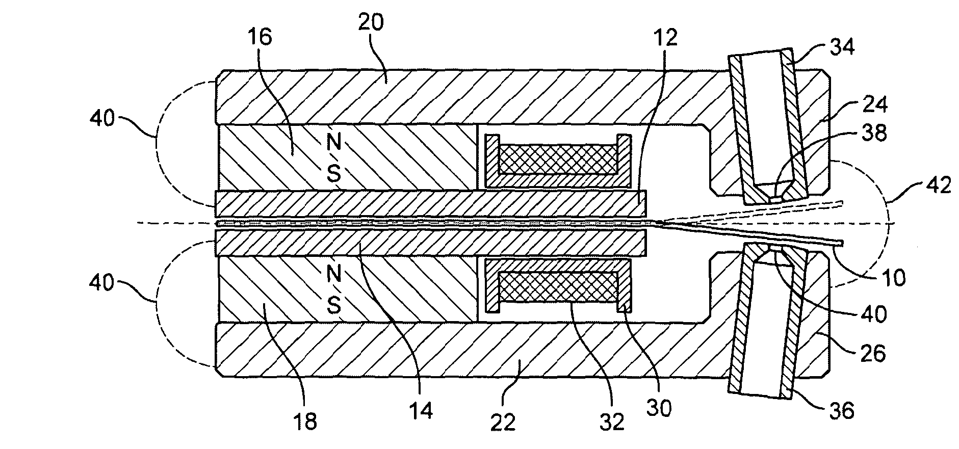
FIELD OF THE INVENTION[0001]The present invention relates to electromagnetically operated switching devices and methods for the operation of such devices. More particularly, it is concerned with improving the magnetic structure of these devices. It is also directed at the provision of sealed fast flow switching devices.BACKGROUND TO THE INVENTION[0002]EP-A-1303719 (filed by the present applicant) describes an electromagnetically operated device of the form shown in present FIG. 1.[0003]A linear armature 10 is sandwiched between two internal pole pieces 12, 14 which are themselves sandwiched between two permanent magnets 16, 18. Two external members 20, 22 extend beyond the end of the sandwich of magnets and at their remote ends provide two inwardly facing poles 24, 26.[0004]The two internal pole pieces 12, 14 extend beyond the permanent magnets 16, 18 where they are surrounded by a coil former 30 on which a coil 32 is wound. Two cylindrical inserts 34, 36 are fitted in the poles 24,...

Claims


Application Information

Patent Timeline
IPC IPC(8): F16K31/06
CPCF16K31/0682F16K31/06F16K31/082F16K31/08
Inventor WYGNANSKI, WLADYSLAW
Owner CAMCON OIL LTD
Learn More