Fully shielded perpendicular recoding writer

a perpendicular recoding and write head technology, applied in the field of magnetic disk systems, can solve the problems of affecting the stability of recording bits, affecting the recording quality of high-speed tracks, and the solution to the problem of wide-spread fringe fields is not quite adequate, so as to achieve the effect of reducing the amount of upstream and downstream flux leakag

Active Publication Date: 2006-05-09
HEADWAY TECH INC
View PDF18 Cites 58 Cited by
  • Summary
  • Abstract
  • Description
  • Claims
  • Application Information

AI Technical Summary

Benefits of technology

[0010]Another object of at least one embodiment of the present invention has been that said writer have minimal upstream and downstream flux leakage.

Problems solved by technology

One of the problems for a PMR writer of the type seen in FIG. 1 is the extent to which its write field spreads to its surroundings, thereby jeopardizing the stability of the recording bits.
However, we have found that this solution to the wide spreading fringe fields problem is not quite adequate.
It is clear that the downstream shield has indeed reduced side fringing in the downstream fields, but there is still a large side fringing field spread on the upstream side, affecting the adjacent track recording bits.
Such a situation is obviously very undesirable for high track density recording.

Method used


Image

  • Fully shielded perpendicular recoding writer
  • Fully shielded perpendicular recoding writer
  • Fully shielded perpendicular recoding writer

Examples


1st embodiment

1st Embodiment

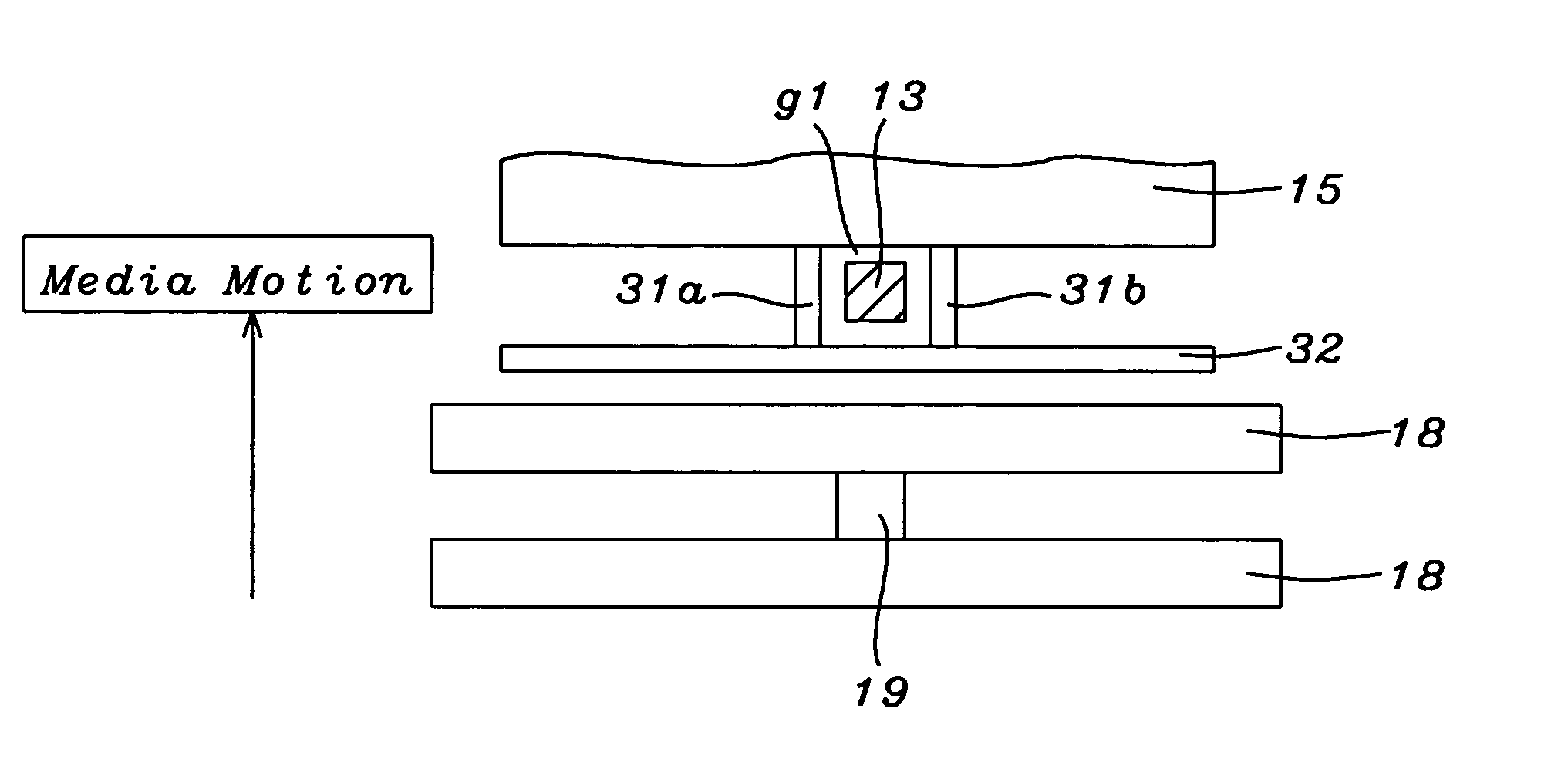
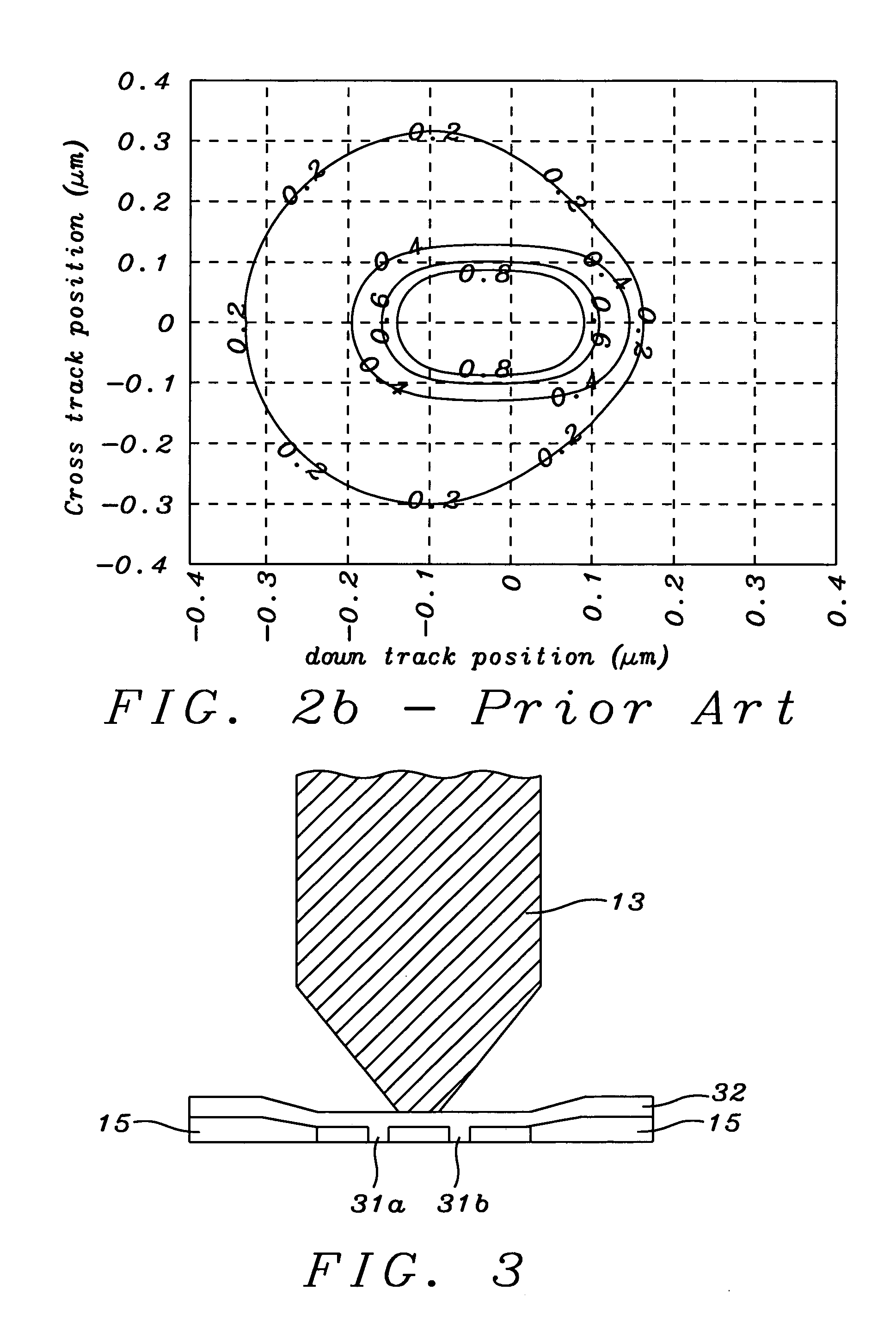
[0022]Referring now to FIG. 3, we show a view of write pole 13 as it would be seen when looking in direction D (of FIG. 1). Also seen in FIG. 3 is downstream shield 15 lying in a plane below that of the figure. This corresponds to what is shown in FIG. 1, but, in a departure from the prior art, upstream shield 32 has been inserted parallel to shield 15 located between write pole 13 and the closest of the two read head shields 18, so that it lies in a plane above that of the figure.

[0023]An important additional novel feature is illustrated in FIG. 4. This is the inclusion of side shields 31a and 31b that magnetically connect the up and down stream shields to one another so the write head is now fully shielded on all four sides. This can be seen more clearly in FIG. 4 which is an ABS view of the structure in the vicinity of the write pole i.e. the view seen when looking up at the Air Bearing Surface (that parallels layer 17).

[0024]The spacing between upstream shield 32 a...

2nd embodiment

2nd Embodiment

[0026]This embodiment is the same in its appearance as the first embodiment when viewed in direction D i.e. as seen in FIG. 3 The differences between the first and second embodiments become clear by looking at FIG. 5 which, like FIG. 4, is an ABS view. In this case, the side shields (now designated as 51) are magnetically connected to downstream shield 15 but do not extend all the way to upstream shield 32. Typically, side shields 51 extend from downstream shield 15 to within 1 micron of upstream shield 32. Because of this, it is necessary that they be thicker than 31a and 31b, typically having thicknesses between about 0.1 and 5 microns.

[0027]For the second embodiment, the upstream leakage outside the side shields is less than about 10% while the downstream leakage outside the side shields is less than about 10%. A detailed field plot for the area immediately around the write pole can be seen in FIG. 6. This much improved magnetic isolation of the write pole makes it ...


PUM

PropertyMeasurementUnit
distanceaaaaaaaaaa
distanceaaaaaaaaaa
distanceaaaaaaaaaa

Abstract

Conventional perpendicular writers that utilize an extended return pole are subject to large flux leakage. This problem has been reduced in the prior art by adding a downstream shield. This still leaves significant upstream leakage. This has now been eliminated by adding an upstream shield and then connecting the up and downstream shields by using side shields. The latter need not extend all the way from the downstream to the upstream shield in which case their thickness is increased relative to the full side shields.

Description

FIELD OF THE INVENTION[0001]The invention relates to the general field of magnetic disk systems with particular reference to magnetic write heads for perpendicular designs, more specifically to flux leakage from the write pole.BACKGROUND OF THE INVENTION[0002]Perpendicular magnetic recording (PMR) is important for the future of the magnetic recording industry because it offers higher areal density than the current longitudinal magnetic recording (LMR). This is due to the fact that the P medium is thermally more stable than that used for LMR. At present, LMR has achieved over 100 Gigabits per square inch (Gbpsi) in the laboratory and more than 60 Gpsi in products currently offered at the market place. In order to further extend the LMR recording density, two main obstacles have to be overcome. The first one is the thermal stability of the LMR recording media which arises because its thickness has to decrease to the extent that thermal energy could randomize the recorded bits. The sec...

Claims


Application Information

Patent Timeline
Patent Type & Authority Patents(United States)
IPC IPC(8): G11B5/127G11B5/31
CPCG11B5/11G11B5/127G11B5/315G11B5/3116G11B5/3146G11B5/1278
Inventor HU, HUNG LIANGTANG, YAW SHINGGUAN, LIJIJU, KOCHAN
Owner HEADWAY TECH INC
Why Eureka
Try Eureka