
Communication device, communication control method, and communication system

Active Publication Date: 2013-06-27
CONVIDA WIRELESS LLC
View PDF11 Cites 13 Cited by
  • Summary
  • Abstract
  • Description
  • Claims
  • Application Information

AI Technical Summary

Benefits of technology

The technology described in this patent helps to prevent or reduce congestion in communication networks used for machine-to-machine communication.

Problems solved by technology

As a result, congestion of traffic within the communication network occurs and a communication failure or deterioration of quality of service (QoS) is likely to be problematic.

Method used


Image

  • Communication device, communication control method, and communication system
  • Communication device, communication control method, and communication system
  • Communication device, communication control method, and communication system

Examples


first embodiment

1. Description of First Embodiment

[0080][1-1. Outline of System]

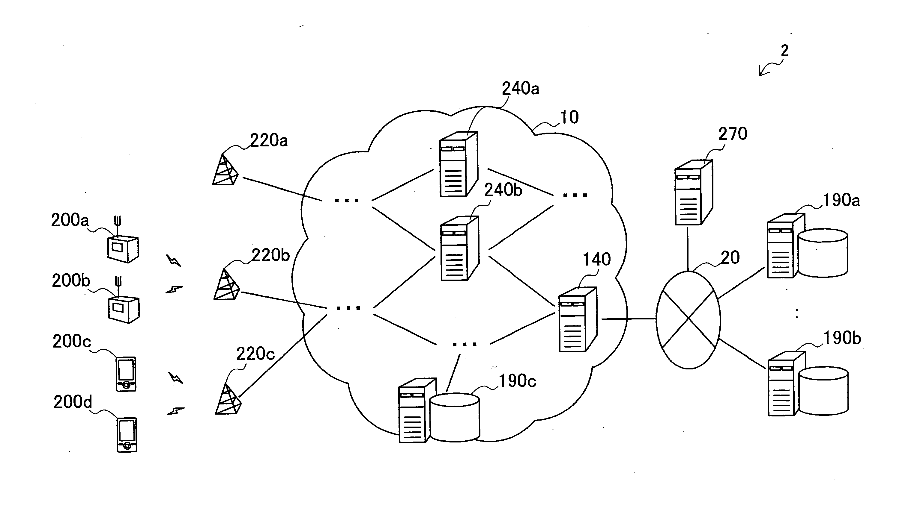
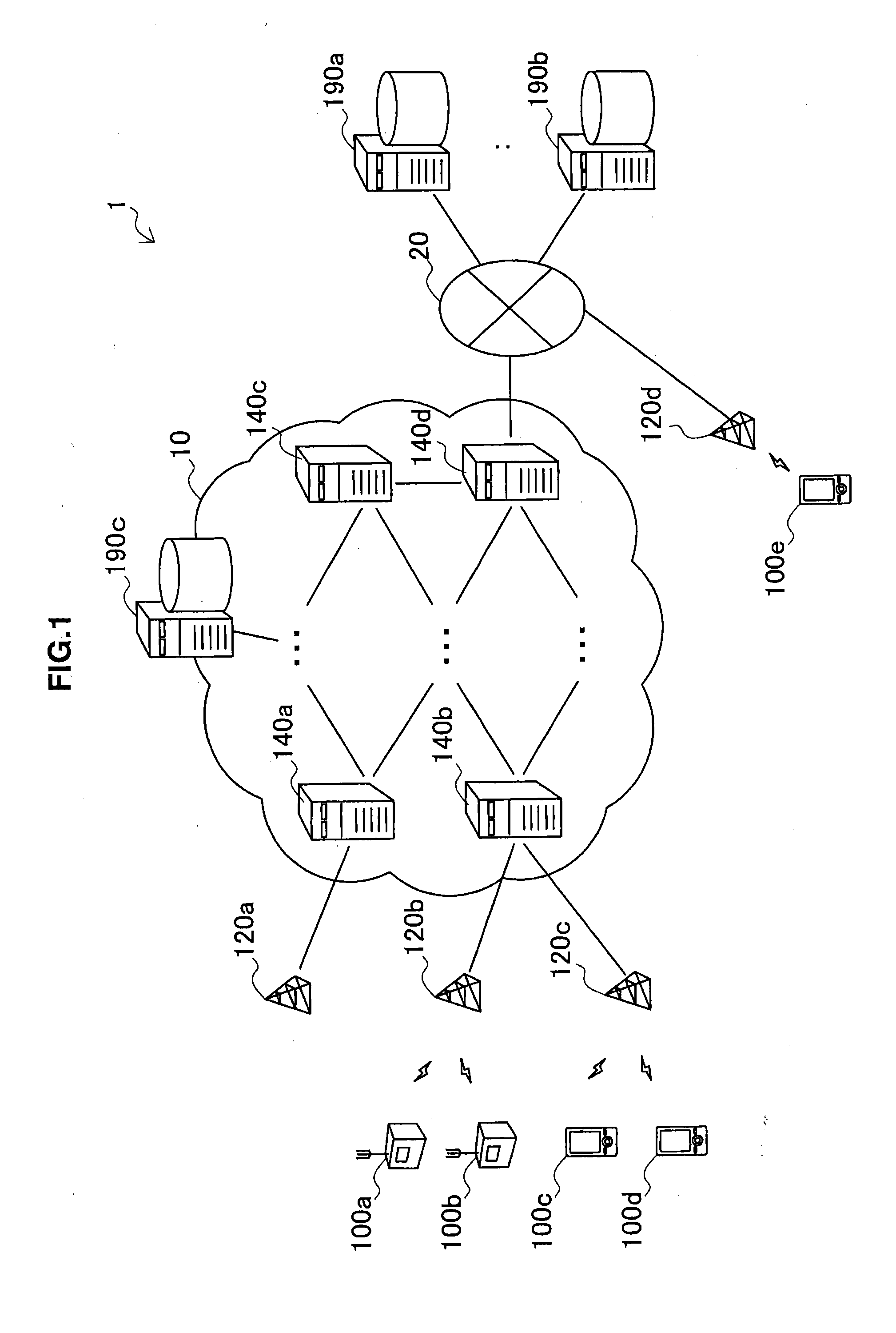
[0081]First, the first embodiment will be described using FIGS. 1 to 9. FIG. 1 is a schematic diagram illustrating an outline of a communication system 1 in accordance with the first embodiment. Referring to FIG. 1, the communication system 1 includes a plurality of terminal devices 100a to 100e, a plurality of base stations 120a to 120d, a plurality of communication devices 140a to 140d, and a plurality of application (AP) servers 190a to 190c. The plurality of communication devices 140a to 140d form a core network 10 in the communication system 1. The base station 120d and the AP servers 190a and 190b are connected to a network 20.

[0082]In this specification, when it is not necessary to distinguish the terminal devices 100a to 100e from one another, they are collectively referred to as a terminal device 100. The same is also true for a base station 120 (120a to 120d), a communication device 140 (140a to 140d), and an ...


PUM


Abstract

Provided is a communication device including a communication control unit that inserts, into a destination field of a data packet, intermediate node designation information designating an intermediate node different from a destination node of the data packet on a path to the destination node, and a transmission unit that transmits the data packet into which the intermediate node designation information is inserted.

Description

TECHNICAL FIELD[0001]The present disclosure relates to a communication device, a communication control method, and a communication system.BACKGROUND ART[0002]Recently, a form of communication referred to as machine-type communication (MTC) communication or machine-to-machine (M2M) communication in which a terminal device connected to a communication network independently performs communication without involving human intervention has been widely used. For example, a household gas meter is used as an MTC terminal and the remaining amount of gas is periodically transmitted from the meter to a server of a provider, so that the provider can recognize an amount of gas used in each household without requiring an inspector to perform a meter reading operation. In addition, the MTC communication, for example, can be used for various purposes such as transmission of an inventory quantity from a vending machine, transmission of the remaining amount of toner from a copier, transportation manag...

Claims


Application Information

Patent Timeline
IPC IPC(8): H04W4/00H04W40/02H04L45/125H04L45/24H04W4/70
CPCH04W4/005H04W40/02H04L45/125H04L47/122H04L47/14H04W28/0289H04L45/306H04L45/34H04L45/24H04W4/70H04W28/02H04L47/2475H04L45/74H04W8/04
Inventor KIMURA, RYOTA
Owner CONVIDA WIRELESS LLC
Learn More