Method for Sealing-in a Gas in a Bag with a Gas Filling Compartment

a gas filling and bag technology, applied in the field of bags can solve the problem that the structure of the conventional bag with gas filling compartments is not suitable for automating, and achieve the effect of efficient operation

Inactive Publication Date: 2013-07-04
TOYO JIDOKI CO LTD
View PDF22 Cites 11 Cited by
  • Summary
  • Abstract
  • Description
  • Claims
  • Application Information

AI Technical Summary

Benefits of technology

[0068]With the use, using also a bag with a gas filling compartment made by the present invention, of the above-described gas seal-in method of the present invention, the process of sealing gas into a gas filling compartment (or an air bag), which has been done almost entirely manually, and the entire packaging process, which includes gas seal-in process, can be performed automatically and performed efficiently.

Problems solved by technology

However, conventional bag with a gas filling compartment does not have a structure suitable for automating the process of sealing gas into the bas filling spaces or for automating the entire packaging process including such a gas sealing process, and the gas sealing process disclosed in, for instance, Japanese Utility Model Application Laid-Open (Kokai) 8-1398 is also not suitable for being automated.

Method used


Image

  • Method for Sealing-in a Gas in a Bag with a Gas Filling Compartment
  • Method for Sealing-in a Gas in a Bag with a Gas Filling Compartment
  • Method for Sealing-in a Gas in a Bag with a Gas Filling Compartment

Examples


Embodiment Construction

[0080]The present invention will now be described specifically with reference to FIGS. 1(a) to 11(c).

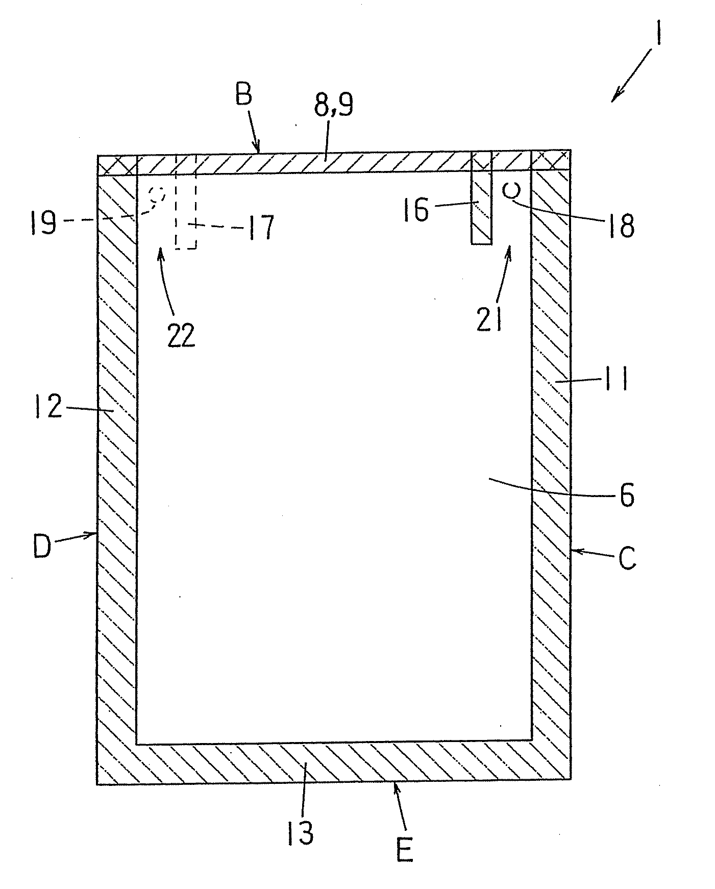
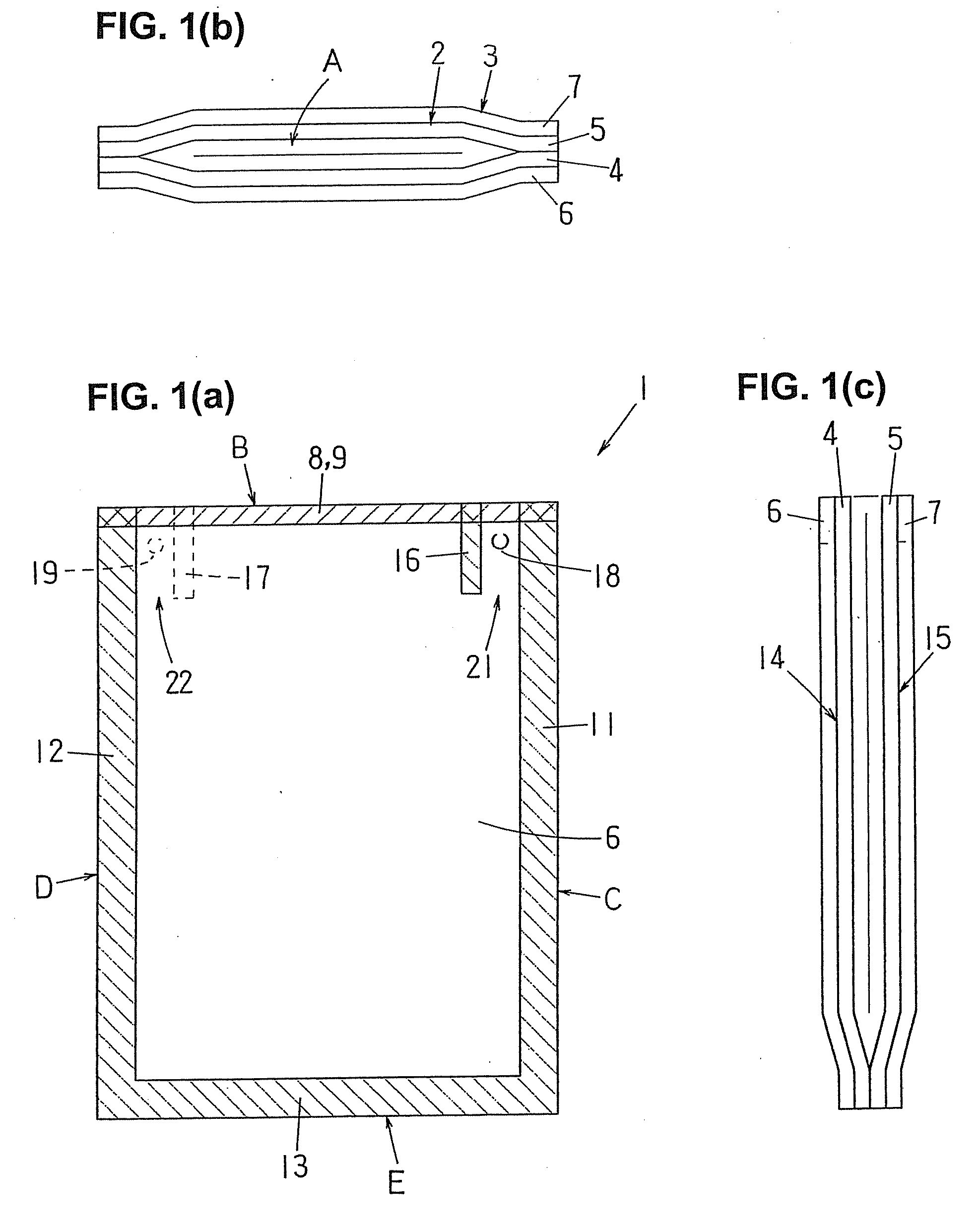
[0081]In FIGS. 1(a) through 1(c), a bag with a gas filling compartment 1 is shown. The bag 1 comprises an inner bag 2 and an outer bag 3 of the substantially same width, the bag mouth (opening) A of the inner bag 2 is open.

[0082]The films 4 and 5 of the inner bag 2 and films 6 and 7 of the outer bag 3 are sealed together along the upper edges thereof on each side of the respective bags (in other words, the adjacent film 4 of the inner bag 2 and film 6 of the outer bag 3 both on one side are sealed together to form a sealed portion 8, and the adjacent film 5 of the inner bag 2 and film 7 of the outer bag 3 both on another side are sealed together to form a sealed portion 9), along the upper edge B of the bag 1. These sealed portions 8 and 9 are indicated by crosshatching in FIG. 1(a).

[0083]Along the two lateral side edges C and D and lower edge E of the bag 1, moreover, the films 4 an...


PUM


Abstract

A method for sealing-in a gas in a bag that has therein a gas filling compartment, including the steps of: placing a blow-out port of a nozzle, which is connected to a pressurized gas supply source, against a cut-in or a hole of the bag and holding the back surface side of the bag with a backing member; blowing a gas from the nozzle into the gas filling compartment of the bag through the cut-in or the hole; gripping and thus closing the gas flow path in sealed portions surrounding the periphery of the cut-in or the hole by a blocking gripper while the gas blow-in continues, thus cutting off the flow of the gas between the cut-in or the hole and the inside of the gas filling compartment; and then sealing the cut-in or the hole, thus allowing the gas to be sealed in the gas filling compartment.

Description

BACKGROUND OF THE INVENTION[0001]1. Field of the Invention[0002]The present invention relates to a bag with a gas filling compartment made of an inner bag and an outer bag having a gas filled in between the inner bag and the outer bag to protect the contents packaged inside the inner bag from shock or the like and also relates to a manufacturing method of such a bag and further to a gas filling method in such a bag and a packaging method for such a bag.[0003]2. Description of the Related Art[0004]Bag with a gas filling compartment (or with an air bag) comprising an outer bag and an inner bag that is provided inside the outer bag, made so that a gas is filled in between the inner bag and the outer bag, are commonly known and disclosed in, for instance, Japanese Utility Model Application Laid-Open (Kokai) Nos. 64-2745 and 8-1398; Japanese Patent Application Laid-Open (Kokai) Nos. 64-84869, 2-98563 and 9-132213; and Japanese Patent Nos. 2800034 and 3015323[0005]However, conventional ba...

Claims


Application Information

Patent Timeline
Patent Type & Authority Applications(United States)
IPC IPC(8): F17B1/00B31B50/64
CPCB65B55/20F17B1/00B65D81/03
Inventor YASUHIRA, MASANORI
Owner TOYO JIDOKI CO LTD
Why Eureka
Try Eureka