High performance freezer having cylindrical cabinet

a technology of high-performance freezers and cylindrical cabinets, which is applied in the field of freezers, can solve the problems of significant floor space or clearance, significant heat energy, and requires a relatively long time for the refrigeration system, and achieve the effect of increasing storage configuration and capacity

Inactive Publication Date: 2013-08-08
THERMO FISHER SCI ASHEVILLE
View PDF25 Cites 30 Cited by
  • Summary
  • Abstract
  • Description
  • Claims
  • Application Information

AI Technical Summary

Benefits of technology

[0014]In yet another aspect, the freezer includes a plurality of vertically oriented dividers extending radially outwardly from adjacent the elongated shaft so as to divide the plurality of shelves into a plurality of shelf compartments. These vertically oriented dividers may be positioned to provide selective access to one of the shelf compartments in a particular shelf when the door of the freezer is opened, while blocking access to adjacent shelf compartments on the particular shelf. Additionally, a plurality of racks is insertable into each shelf compartment to further increase storage configurations and capacity within the freezer.

Problems solved by technology

Conventional doors are generally pivotally coupled to the cabinet and therefore require significant floor space or clearance to fully open the door.
Additionally, opening these pivotal doors generally exposes the entire inner chamber to the exterior environment for the duration of the door opening.
Especially when using a two-stage cascade refrigeration system in an ultra-low temperature freezer, exposing the entire inner chamber to the exterior environment adds significant heat energy into the inner chamber that requires a relatively lengthy period of time for the refrigeration system to recover to a desired temperature following the door re-closing.
Furthermore, it can be difficult to access items stored in the back of the inner chamber of these rectangular box shaped freezers.
As described above, this arrangement therefore increases the amount of time that the refrigeration system requires to establish a desired temperature within the inner chamber.

Method used


Image

  • High performance freezer having cylindrical cabinet
  • High performance freezer having cylindrical cabinet
  • High performance freezer having cylindrical cabinet

Examples


Embodiment Construction

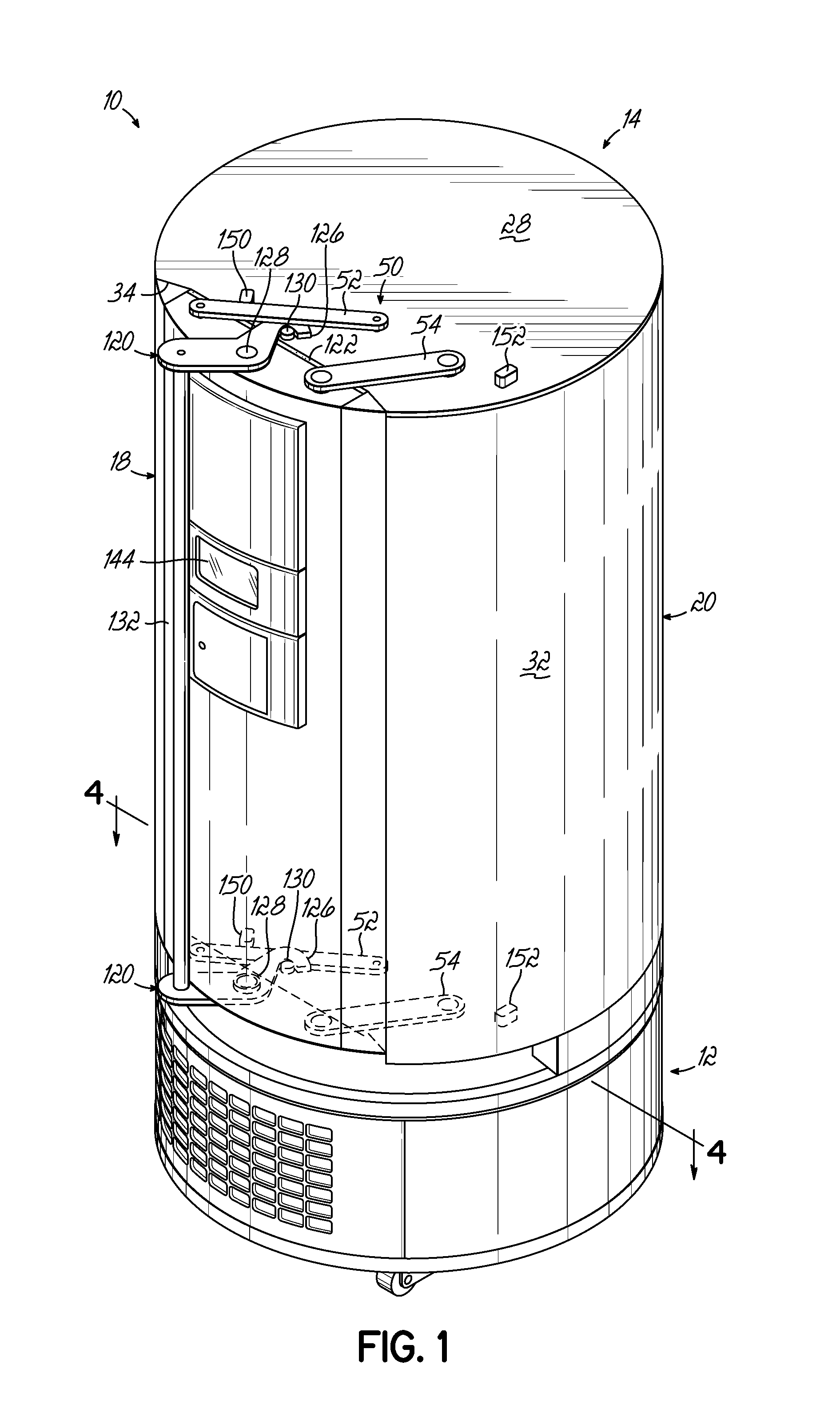
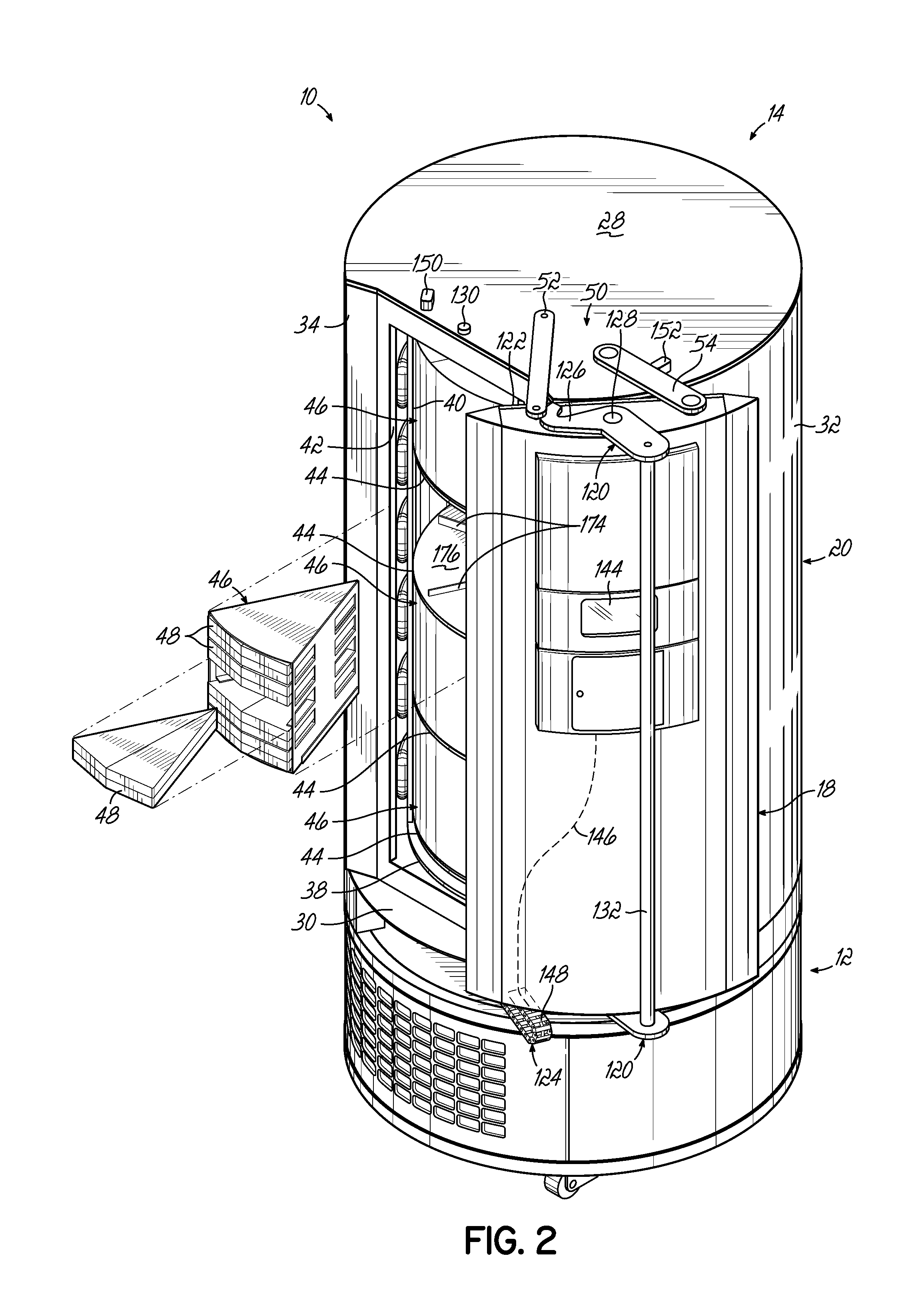
[0039]With reference to the figures, and more specifically to FIGS. 1-15, an exemplary freezer 10 according to one embodiment of the present invention is illustrated. Although the terms “high performance freezer” and “freezer” are used throughout the specification, it will be understood that these terms encompass any type of cooling device, refrigerator, or freezer. The freezer 10 of FIGS. 1 and 2 is in the form of an ultra-low temperature freezer (“ULT”) 10 including a deck 12 that supports a cabinet 14 above the deck 12. As used herein, the term “deck” refers to the structural assembly or framework that is located beneath and supports the cabinet 14. The freezer 10 stores items that require cooling to a desired temperature in the range from about −30° C. to about −80° C., or even lower temperatures, for example. In this regard, the freezer 10 includes a two-stage cascade refrigeration system 16 that cools items stored in the freezer 10 to the desired temperature. Components of the...


PUM


Abstract

A high performance freezer includes a deck and a cabinet supported above the deck and having a cabinet housing defining a generally cylindrical shape. The freezer includes a door supported by the cabinet housing that moves between open and closed positions by sliding or pivoting generally along the side wall of the cabinet. The freezer further includes a refrigeration system mounted at least partially within the deck and partially within the cabinet to refrigerate an inner chamber of the freezer. The cylindrical shape of the cabinet enables rotation of shelves within the inner chamber and a maximized storage space with a minimal floor space required.

Description

FIELD OF THE INVENTION[0001]The present invention relates generally to freezers and, more particularly, to high performance freezers operable to cool an inner chamber to a range from about −30° C. to about −80° C., or lower.BACKGROUND OF THE INVENTION[0002]Refrigeration systems are known for use with laboratory refrigerators and freezers of the type known as “high performance freezers,” which are used to cool their interior storage spaces to relatively low temperatures such as about −30° C. or lower, for example. One type of high performance freezer is known as an “ultra-low temperature freezer” (“ULT”), which is used to cool its inner storage chamber to relatively low temperatures such as about −80° C. or lower, for example.[0003]Known refrigeration systems of this type include two stages circulating respective first and second refrigerants. The first stage receives energy (i.e., heat) from the cooled space (e.g., a cabinet inner chamber) through an evaporator circulating the first...

Claims


Application Information

Patent Timeline
Patent Type & Authority Applications(United States)
IPC IPC(8): F25D23/02F25D11/00F25B7/00
CPCF25B7/00F25B40/04F25D23/02F25D11/00F25D11/04F25D23/028F25D25/027
Inventor NATARAJAN, MAHESHINGLE, TUSHARKHADTKAR, RAJENDRA
Owner THERMO FISHER SCI ASHEVILLE
Why Eureka
Try Eureka