Fluorescent microscope for observing multiple fluorescent images, fluorescent image surveying method using the same, and multiple fluorescent image observing system

a fluorescent microscope and fluorescent image technology, applied in the field of fluorescent microscopes for observing multiple fluorescent images, can solve the problems of inability to irradiate various kinds of light, breakdown of devices, and difficulty in promptly and simply obtaining the desired fluorescent image, and achieve the effect of simple and quick observation

Active Publication Date: 2013-08-08
NANOENTEK
View PDF5 Cites 8 Cited by
  • Summary
  • Abstract
  • Description
  • Claims
  • Application Information

AI Technical Summary

Benefits of technology

[0036]According to the present invention, the fluorescent microscope for observing multiple fluorescent images includes a plurality of image acquisition units corresponding to the number of light sources from which light is irradiated, whereby a plurality of fluorescent images can be simply and promptly observed without a mechanical movement.

Problems solved by technology

However, the fluorescent microscope according to the related art is configured to obtain a single fluorescent image according to the light irradiated to the sample 17, and is unsuitable for irradiating various kinds of light to obtain fluorescent images and then comparing the fluorescent images to survey an accurate shape of the sample 17.
That is, the multi fluorescent microscope requires separate electronic and mechanical equipment to replace a light source and a filter, requiring high production costs, generates mechanical vibrations, causing a breakdown of the device, and consumes a separate time for replacing a light source and a filter, making it difficult to promptly and simply obtain a desired fluorescent image.

Method used


Image

  • Fluorescent microscope for observing multiple fluorescent images, fluorescent image surveying method using the same, and multiple fluorescent image observing system
  • Fluorescent microscope for observing multiple fluorescent images, fluorescent image surveying method using the same, and multiple fluorescent image observing system
  • Fluorescent microscope for observing multiple fluorescent images, fluorescent image surveying method using the same, and multiple fluorescent image observing system

Examples


first embodiment

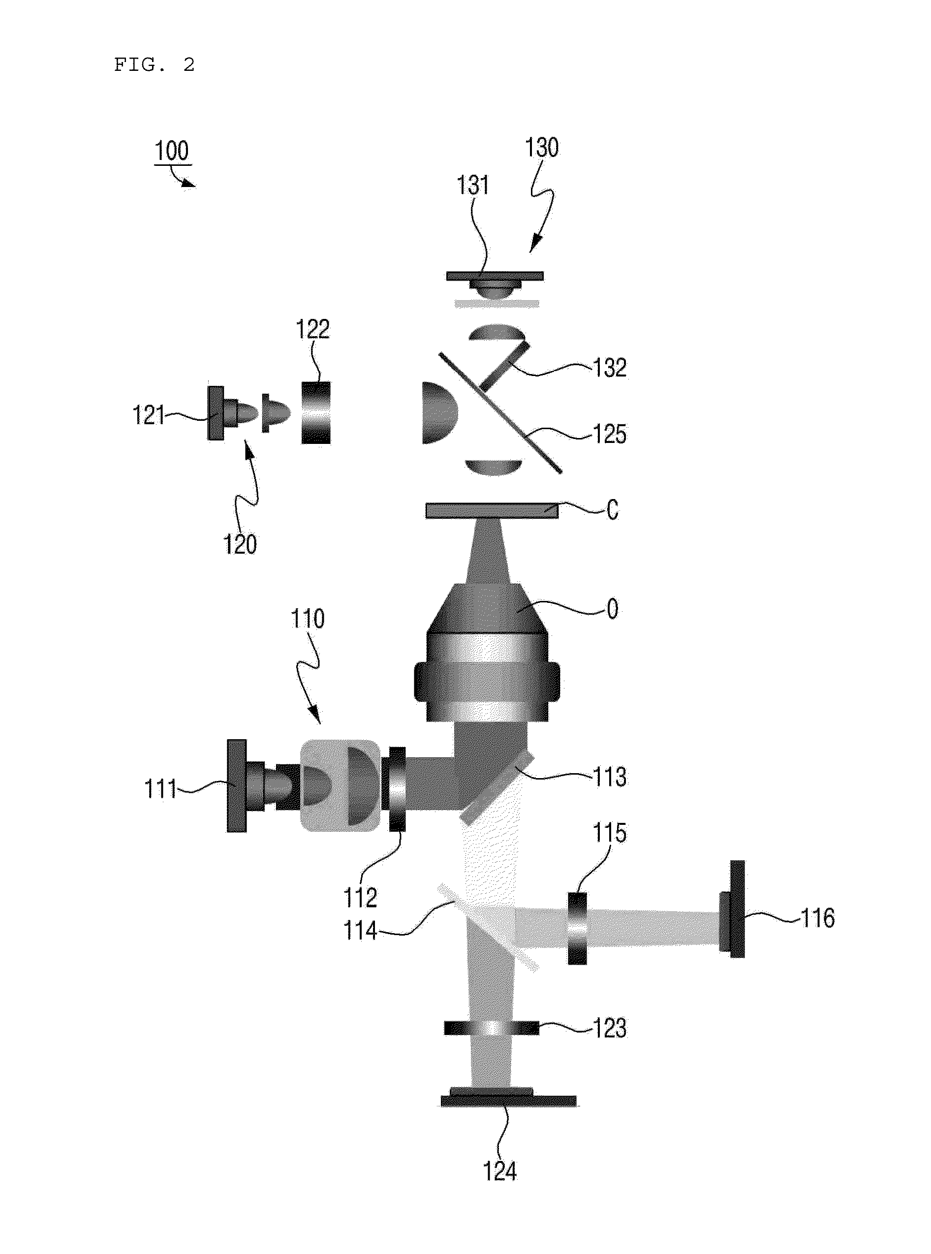
[0038]FIG. 2 is a schematic diagram illustrating a fluorescent microscope according to the present invention;

[0039]FIG. 3 is a schematic diagram illustrating a principle of acquiring an image of a survey object with a first optical module of the fluorescent microscope of FIG. 2;

[0040]FIG. 4 is a schematic diagram illustrating a principle of acquiring an image of a survey object with a second optical module of the fluorescent microscope of FIG. 2;

[0041]FIG. 5 is a schematic diagram illustrating a principle of acquiring an image of a survey object with a third optical module of the fluorescent microscope of FIG. 2;

second embodiment

[0042]FIG. 6 is a schematic diagram illustrating a fluorescent microscope according to the present invention;

[0043]FIG. 7 is a schematic diagram illustrating a principle of acquiring an image of a survey object with a first optical module of the fluorescent microscope of FIG. 6;

[0044]FIG. 8 is a schematic diagram illustrating a principle of acquiring an image of a survey object with a second optical module of the fluorescent microscope of FIG. 6;

[0045]FIG. 9 is a schematic diagram illustrating a principle of acquiring an image of a survey object by using a third optical light source of the fluorescent microscope of FIG. 2;

third embodiment

[0046]FIG. 10 is a schematic diagram illustrating a fluorescent microscope according to the present invention;

[0047]FIG. 11 is a schematic diagram illustrating a principle of acquiring an image of a survey object with a first optical module of the fluorescent microscope of FIG. 10;

[0048]FIG. 12 is a schematic diagram illustrating a principle of acquiring an image of a survey object with a second optical module of the fluorescent microscope of FIG. 10;

[0049]FIG. 13 is a schematic diagram illustrating a principle of acquiring an image of a survey object by using a third optical light source of the fluorescent microscope of FIG. 10;


PUM


Abstract

A fluorescent microscope for observing multiple fluorescent images includes: a first optical module comprising a first light source for supplying first excitation light having a first wavelength, a first excitation filter for selectively transmitting the first excitation light supplied from the first light source, a first dichroic filter for reflecting the first excitation light having passed through the first excitation filter toward the survey object, an objective lens for condensing the first excitation light reflected by the first dichroic filter and transferring the condensed first excitation light to the survey object, a second dichroic filter for reflecting first radiation light radiated from the survey object, a first radiation filter for selectively transmitting the first radiation light reflected by the second dichroic filter, and a first image acquisition unit for acquiring an image by using the first radiation light having passed through the first radiation filter to be supplied; and a second optical module comprising a second light source for supplying second excitation light having a second wavelength, a second excitation filter for selectively transmitting the second excitation light supplied from the second light source, a second radiation filter passing through the second excitation filter and irradiated to the survey object to be radiated, to selectively transmitting the second radiation light EM2 having passed through the objective lens, the first dichroic filter, and the second excitation filter, and a second image acquisition unit for acquiring an image by using the second radiation light having passed through the second radiation filter to be supplied.

Description

TECHNICAL FIELD[0001]The present invention relates to a fluorescent microscope for observing multiple fluorescent images, a fluorescent image surveying method using the same, and a multiple fluorescent image observing system, and more particularly, to a fluorescent microscope for observing multiple fluorescent images by which a plurality of fluorescent images can be simply and promptly observed without a mechanical movement, a fluorescent image surveying method using the same, and a multiple fluorescent image observing system.BACKGROUND ART[0002]A fluorescent microscope refers to an apparatus which processes a fluorescent material (fluorescent pigment) in a sample by using a principle in which fluorescent light is emitted from a fluorescent substance if the fluorescent substance absorbs light having a specific wavelength, and irradiates light having the absorption wavelength of the fluorescent material to the sample to survey the sample through radiation light emitted from the sampl...

Claims


Application Information

Patent Timeline
Patent Type & Authority Applications(United States)
IPC IPC(8): G02B21/00
CPCG02B21/0064G02B21/0076G02B2207/113G01N2021/6419G01N2021/6421G02B21/16G01N21/64G02B21/00
Inventor PARK, HWA JOONHWANG, JEOUNG KUKIM, JEE YOUNGCHUNG, CHAN IL
Owner NANOENTEK
Why Eureka
Try Eureka