Micro-fluidic pump

Inactive Publication Date: 2013-08-08
LEXMARK INT INC
View PDF5 Cites 18 Cited by
  • Summary
  • Abstract
  • Description
  • Claims
  • Application Information

AI Technical Summary

Benefits of technology

[0013]In representative embodiments, the pump is operated by activating the heaters inside the channel in a predetermined way. The heaters are fired with a fire-to-fire

Problems solved by technology

Among these components, it is well known to be difficult to attain micro-fluidic pumps which are ready to be assembled with micro-fluidic devices at low costs.
For example, while a range of micro-fluidic devices have been miniaturized to the size of a postage stamp, these devices have often required large external pneumatic pumping systems for their operation.
Usually, these pumps have complex structures and are difficult to manufactur

Method used


Image

  • Micro-fluidic pump
  • Micro-fluidic pump
  • Micro-fluidic pump

Examples


Embodiment Construction

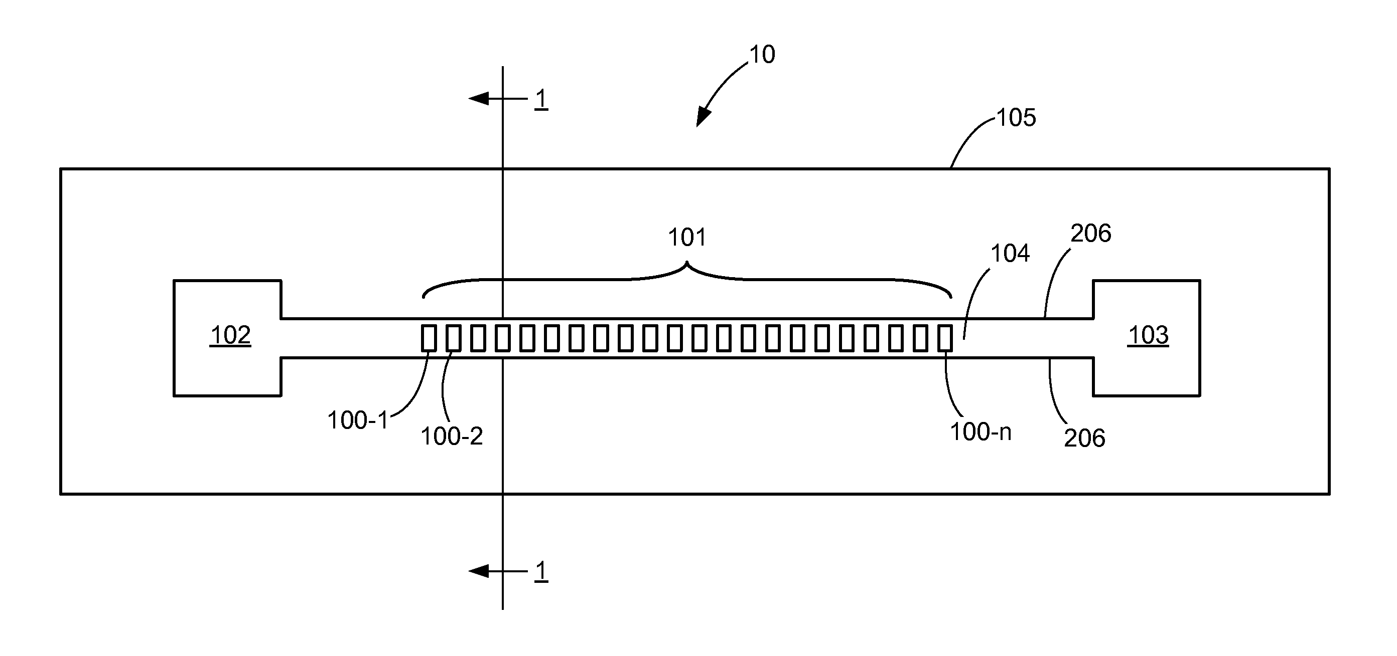
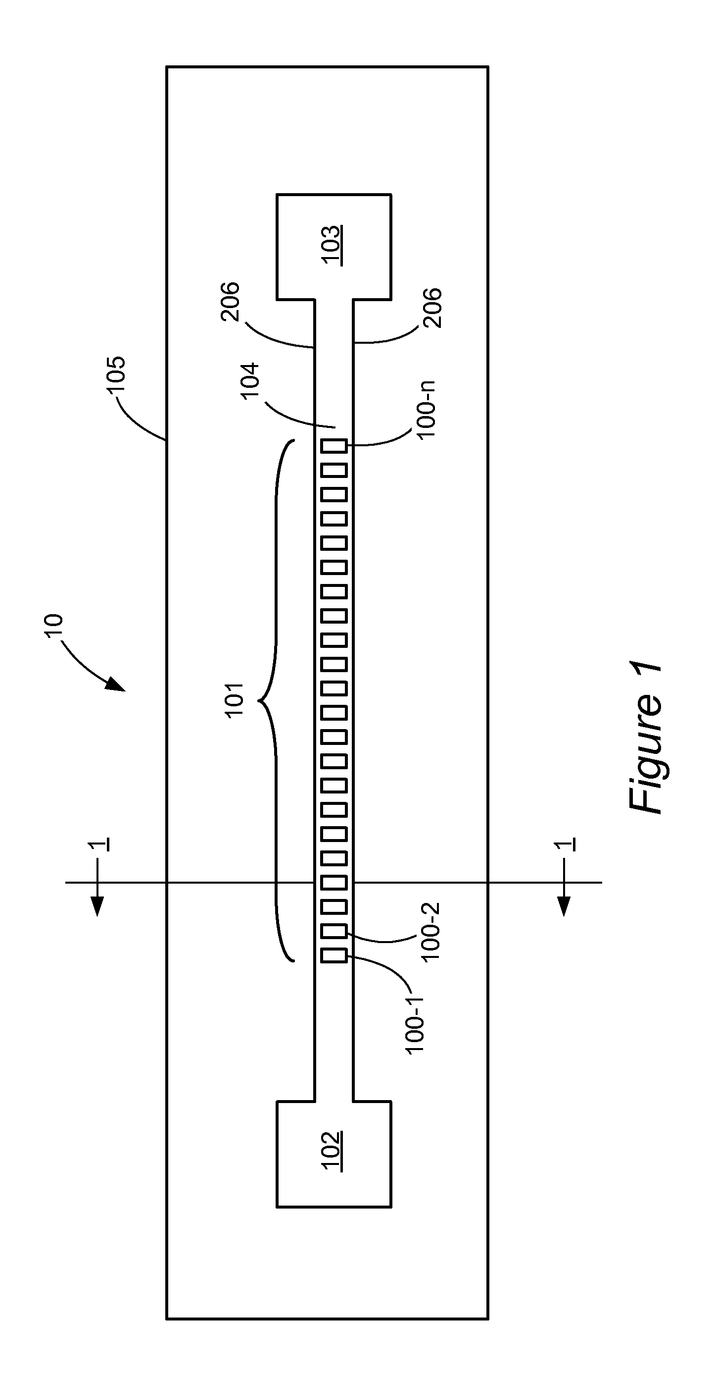
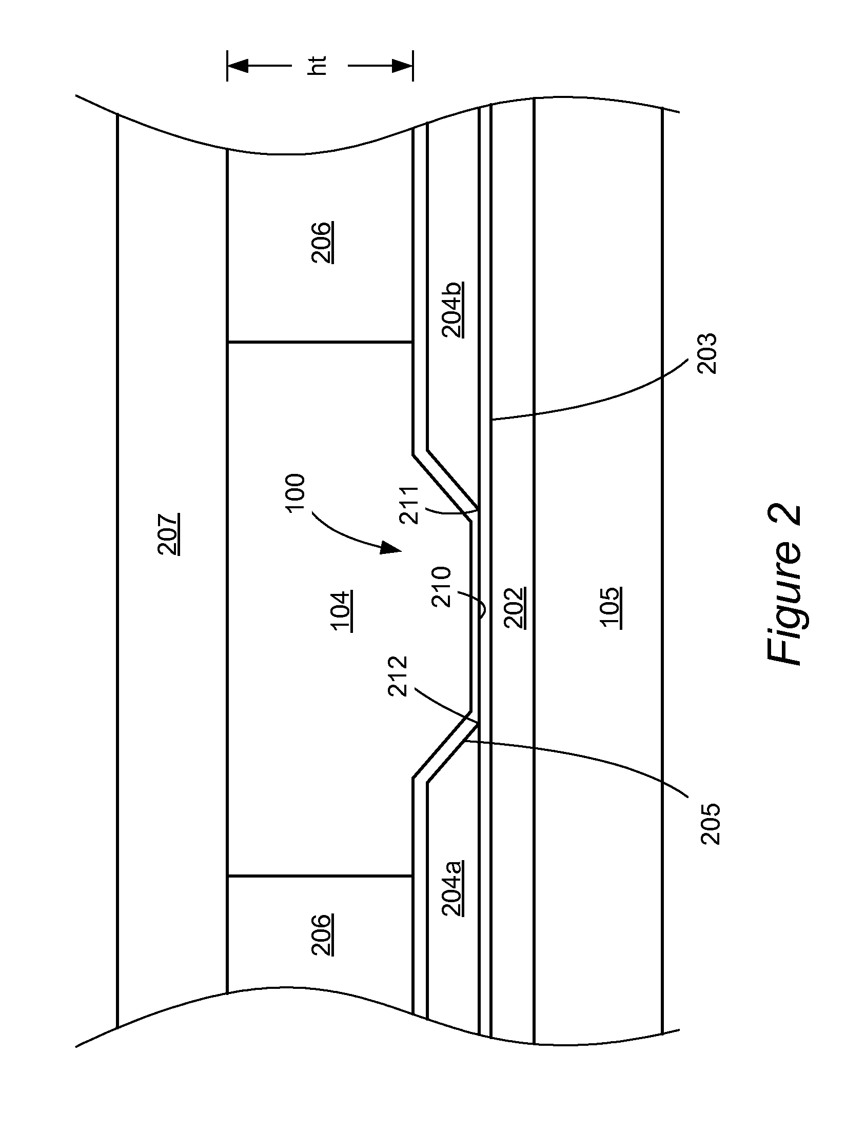
[0023]The following describes a pump which forms thermal bubbles in order to transport liquid through channels or deliver liquid from a reservoir to channels in micro-fluidic devices and a method for using the pump to achieve a predetermined pumping rate and minimize the thermal effects of the pump to the liquid transported.

[0024]In many micro-fluidic applications such as liquid dispensing, point-of-care diagnostics or lab-on-a-chip, a role of micro-fluidic pumps is to manipulate micro-volumes of a variety of liquids inside micro-channels. In many cases, liquids used for these applications are heat sensitive. For example, blood cells can be degraded at temperature above 50° C. For this reason, when a micro-fluidic pump exploiting thermal bubbles is applied to transport liquid in a micro-fluidic device, it should be considered how to prevent overheating of the liquid.

[0025]Thermal bubbles from a liquid can be formed by either normal boiling or supercritical heating. When the temperat...


PUM


Abstract

A micro-fluidic pump comprises one or more channels having an array of resistive heaters, an inlet, outlet and a substrate as a heat sink and a means of cooling the device. The pump is operated with a fire-to-fire delay and/or a cycle-to-cycle delay to control the pumping rate and minimize heating of liquid inside the pump during its operation.

Description

CROSS REFERENCES TO RELATED APPLICATIONS[0001]This application claims the benefit and priority of U.S. provisional patent application Ser. No. 61 / 594,559, filed Feb. 3, 2012, entitled Micro-Fluidic Pump, whose contents are incorporated herein by reference as if set forth herein.STATEMENT REGARDING FEDERALLY SPONSORED RESEARCH OR DEVELOPMENT[0002]NoneREFERENCE TO SEQUENTIAL LISTING, ETC.[0003]NoneBACKGROUND[0004]1. Field of the Disclosure[0005]This present disclosure generally relates to a pump. More specifically, it relates to a pump which forms thermal bubbles to transport liquid through a channel or deliver liquid from a reservoir to a channel of micro-fluidic devices. Resistive heaters configured to flow fluid in channels about a chip facilitate certain designs, as do techniques for controlling them. Thermal control facilitates other designs.[0006]2. Description of the Related Art[0007]Micro-fluidic devices manipulate microscopic volumes of liquid inside micro-sized structures. A...

Claims


Application Information

Patent Timeline
IPC IPC(8): F04B19/24
CPCF04B19/24F04B19/006F28F3/12
Inventor HONG, EUNKIBERGSTEDT, STEVENGUAN, YIMIN
Owner LEXMARK INT INC
Why Eureka
Try Eureka