Plasma display apparatus and driving method thereof

A display device, plasma technology, applied in identification devices, static indicators, instruments, etc., can solve problems such as increased power consumption and drive device load, influence, reliability and unfavorable operation of plasma display panels, and achieves increased brightness, guaranteed The effect of reliability and stable operation

Inactive Publication Date: 2006-02-01
LG ELECTRONICS INC
View PDF0 Cites 0 Cited by
  • Summary
  • Abstract
  • Description
  • Claims
  • Application Information

AI Technical Summary

Problems solved by technology

[0012] However, increasing the number of sustain pulses Sus to enhance brightness will result in increased power consumption and more heat generation of the plasma display panel and its driving circuit
These problems reduce the reliability of plasma display panels and produce afterimages
Moreover, these problems increase the power consumption and the load on the driving device, adversely affecting the reliability and operation of the plasma display panel

Method used


Image

  • Plasma display apparatus and driving method thereof
  • Plasma display apparatus and driving method thereof
  • Plasma display apparatus and driving method thereof

Examples


no. 1 example

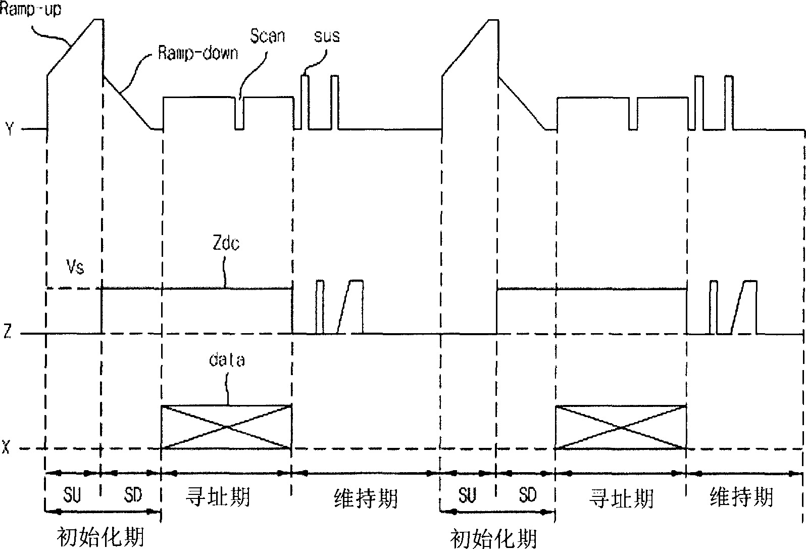
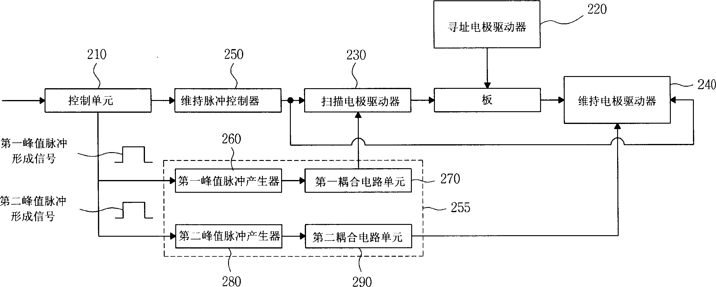
[0067] image 3 A circuit composed of a first peak generator, a second peak generator, a first coupling circuit unit, a second coupling circuit unit, and an electrode driver included in a plasma apparatus according to the present invention according to a first embodiment of the present invention structure. Figure 4 is the first embodiment of the sustain pulse waveform according to the present invention.

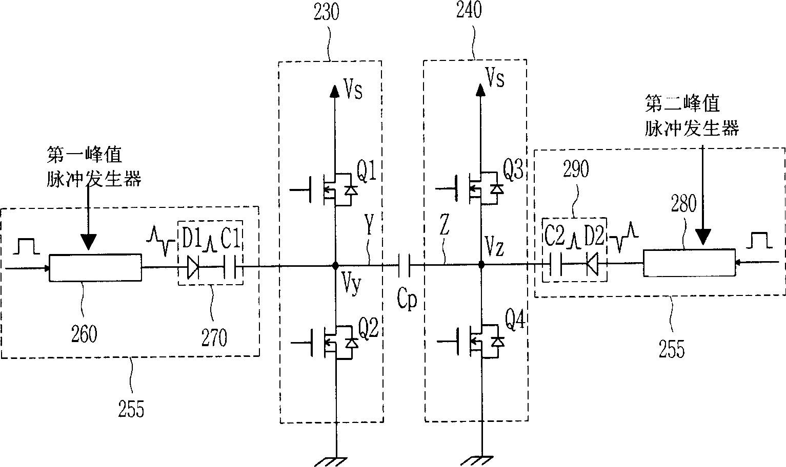
[0068] like image 3 As shown, the first peak pulse generator 260 receiving the first peak pulse forming signal with a rectangular waveform from the control unit 210 outputs a positive peak pulse with a trigger pulse waveform and a negative peak pulse with a trigger pulse waveform.

[0069] The first coupling circuit unit 270 includes a first diode D1 and a first capacitor C1. The anode of the first diode D1 is connected to the first peak pulse generator 260 and the cathode of the first diode D1 is connected to one end of the first capacitor C1. Moreover, the other end o...

no. 2 example

[0081] Figure 5 A circuit composed of a first peak generator, a second peak generator, a first coupling circuit unit, a second coupling circuit unit, and an electrode driver included in a plasma apparatus according to the present invention according to a second embodiment of the present invention structure. Figure 6 is the second embodiment of the sustain pulse waveform according to the present invention.

[0082] exist image 3In the shown first embodiment, the scan electrode driver 230 and the sustain electrode driver 240 do not include an energy recovery circuit, but in Figure 5 In the illustrated second embodiment, the scan electrode driver 230 and the sustain electrode driver 240 include a first energy recovery circuit 235 and a second energy recovery circuit 245, respectively.

[0083] Therefore, at the first energy supply / recovery capacitor C er1 or a second energy supply / restoration capacitor C er2 When the sustain voltage is applied after the energy is supplie...


PUM


Abstract

Provided are an apparatus and method for driving a plasma display panel, which are capable of increasing the brightness of the plasma display panel and minimizing power consumption and the amount of heat generation without increasing the number of sustain pulses. The plasma display apparatus includes: a plasma display panel including a scan electrode and a sustain electrode; a scan electrode driver for applying a first sustain pulse to the scan electrode; a sustain electrode driver applying a second sustain pulse to the sustain electrode alternately with the first sustain pulse; and a peak pulse applying unit causing a peak pulse to overlap the first sustain pulse and the second sustain pulse when the first sustain pulse and the second sustain pulse are alternately applied to the scan electrode and the sustain electrode.

Description

[0001] This application claims priority from Patent Application No. 2004-0058925 filed in Korea on Jul. 27, 2004, the entire contents of which are hereby incorporated by reference. technical field [0002] The present invention relates to a plasma display device and its driving method, in particular to a device and a method for driving a plasma display panel by using a peak pulse. Background technique [0003] figure 1 Shown are the driving waveforms used in conventional plasma display panels. refer to figure 1 , the conventional plasma display panel is driven according to a reset period (ie, an initialization period) for initializing the entire screen, an address period for selecting cells, and a sustain period for maintaining the discharge of the selected cells. [0004] During the initialization period, in the rising period SU, the ramp-up pulse Ramp-up is applied to all the scan electrodes Y at the same time. Thus, a dull discharge (that is, an initial discharge) is g...

Claims


Application Information

Patent Timeline
Patent Type & Authority Applications(China)
IPC IPC(8): G09G3/28H01J17/49G09F9/313G09G3/294G09G3/20G09G3/291G09G3/296
CPCG09G3/288G09G2310/0267G09G2330/024G09G2320/02G09G3/2948G09G2310/06G09G3/2942G09G3/2965G09G3/296
Inventor 文圣学
Owner LG ELECTRONICS INC
Why Eureka
Try Eureka