Fuel cell system

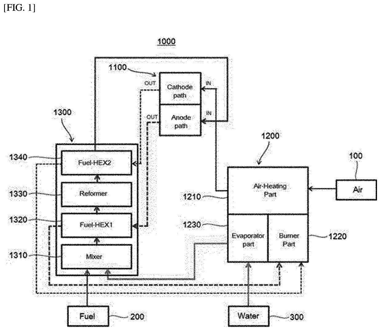
a fuel cell and system technology, applied in the direction of generator/motor, electrochemical generator, generator and heating apparatus, etc., can solve problems such as safety problems, and achieve the effects of minimizing the length of the pipe connecting the components to each other in each module, reducing differential pressure and heat loss, and simplifying the assembly process of the system

Active Publication Date: 2022-01-11
MICO POWER LTD
View PDF14 Cites 0 Cited by
  • Summary
  • Abstract
  • Description
  • Claims
  • Application Information

AI Technical Summary

Benefits of technology

[0006]A purpose of the present disclosure is to provide a fuel cell system that may not only improve thermal efficiency, but also improve reforming efficiency and electricity generation efficiency.
[0020]In the fuel cell system according to the present disclosure, the heat-transfer device, the burner and the water-vapor generator are collected to form the first module, and the mixer, the first heat exchanger, the reformer and the second heat exchanger are collected to form the second module. Thus, a length of a pipe connecting the components to each other in each module may be minimized, thereby to minimize differential pressure and heat loss, as well as simplify an assembly process of the system and allow easy maintenance.
[0021]Moreover, the first module heats the air and generates the water vapor using one combustion device that burns the unreacted fuel gas and air, thereby to improve thermal efficiency. The water-vapor generator is capable of reducing the pressure-pulsation, such that the fuel gas may be uniformly supplied to the fuel cell module. Further, since the mixed fuel gas heated via the heat exchange is supplied to the reformer, and the reformed fuel gas is heated again via heat exchange and then is supplied to the fuel cell module, reforming efficiency and electricity generation efficiency may be improved.

Problems solved by technology

However, installing a hydrogen storage tank directly where the fuel cell is installed causes a safety problem.

Method used


Image

  • Fuel cell system
  • Fuel cell system
  • Fuel cell system

Examples


Embodiment Construction

[0025]Hereinafter, embodiments of the present disclosure will be described in detail with reference to the accompanying drawings. The present disclosure may be modified in various ways and may take many forms. Specific embodiments are illustrated in the drawings and described in detail herein. However, the embodiments are not intended to limit the present disclosure thereto. It should be understood that all changes, equivalents, or substitutes thereto are included in scope and spirit of the present disclosure. In describing the drawings, similar reference numerals are used for similar components. In the accompanying drawings, dimensions of structures are shown to be enlarged than actual ones for clarity of the present disclosure.

[0026]It will be understood that, although the terms “first”, “second”, “third”, and so on may be used herein to describe various elements, components, regions, layers and / or sections, these elements, components, regions, layers and / or sections should not be...


PUM

PropertyMeasurementUnit
temperatureaaaaaaaaaa
electric energyaaaaaaaaaa
heightaaaaaaaaaa

Abstract

A fuel cell system is disclosed. The fuel cell system includes: a fuel cell module including a plurality of unit cells for generating electrical energy by using oxygen of air and hydrogen of a reformed fuel gas; a first module including a burner part which burns an unreacted fuel gas and air discharged from the fuel cell module, an air-heating part which heats air through heat exchange with a hot combustion gas and a flame generated by the burner part and supplies the heated air to the fuel cell module, and a water vapor generation part which converts water, flowing through an inner portion thereof, into water vapor through heat exchange with a hot combustion gas generated by the burner part; and a second module which mixes a fuel supplied from an external fuel supply source and water vapor supplied from a water-vapor generator part.

Description

CROSS REFERENCE TO RELATED APPLICATIONS[0001]This application is a national phase under 35 U.S.C. § 371 of International Application No. PCT / KR2019 / 005006, filed Apr. 25, 2019, which claims the benefit of priority to Korean Patent Application Serial No. 10-2018-0048765, filed Apr. 26, 2018. The contents of the referenced applications are incorporated into the present application by reference.FIELD OF THE INVENTION[0002]The present disclosure relates to a fuel cell system that generates electrical energy using hydrocarbon fuel and air.DESCRIPTION OF RELATED ART[0003]A fuel cell generates electricity using reaction between hydrogen and oxygen. The fuel cell has the highest efficient when using hydrogen directly. However, installing a hydrogen storage tank directly where the fuel cell is installed causes a safety problem. Therefore, at present, hydrocarbon fuel is reformed to produce hydrogen which in turn is used as fuel in the fuel cell. A method of reforming the hydrocarbon fuel inc...

Claims


Application Information

Patent Timeline
Patent Type & Authority Patents(United States)
IPC IPC(8): H01M8/0612C01B3/38H01M8/04014H01M8/04007F24D18/00
CPCH01M8/0618C01B3/384H01M8/04022H01M8/04067C01B2203/0822Y02E60/50H01M8/0662H01M8/04074C01B3/34C01B2203/066C01B2203/1276F28D7/082F28D21/0003F28D2021/0043F28D7/024F28D2021/0064F24H3/087F24H1/145F22B1/1869F28F9/22F28F2009/226F24D2200/19F24D2101/30F24D2103/13F24D18/00H01M8/04014H01M8/0631H01M8/04201H01M2008/1293H01M2008/147
Inventor CHOI, SONG HOLEE, JUN WOO
Owner MICO POWER LTD
Why Eureka
Try Eureka