Linear stapler

a linear stapler and end effector technology, applied in the field of surgical stapling and cutting instruments, can solve the problem of economic inefficiency of replacing an entire end effector for each operation

Inactive Publication Date: 2013-08-15
CILAG GMBH INT
View PDF8 Cites 383 Cited by
  • Summary
  • Abstract
  • Description
  • Claims
  • Application Information

AI Technical Summary

Benefits of technology

[0007]The present invention relates to a linear stapler incorporating a cartridge with a lockout which can prevent a used or spent cartridge from refiring.

Problems solved by technology

Replacing an entire end effector for each operation tends to be economically inefficient.

Method used


Image

  • Linear stapler
  • Linear stapler
  • Linear stapler

Examples


Embodiment Construction

[0037]For convenience and ease of understanding, like parts are indicated by like reference signs in the context. It will be appreciated that the terms “proximal” and “distal” are used herein with reference to a user gripping a handle of an instrument. Thus, an end effector is distal with respect to a more proximal handle. It will be further appreciated that, for convenience and clarity, spatial terms such as “vertical” and “horizontal”, “up” and “down” are used herein with respect to the drawings. However, surgical instruments are used in many orientations and positions, and these terms are not intended to be limiting and absolute.

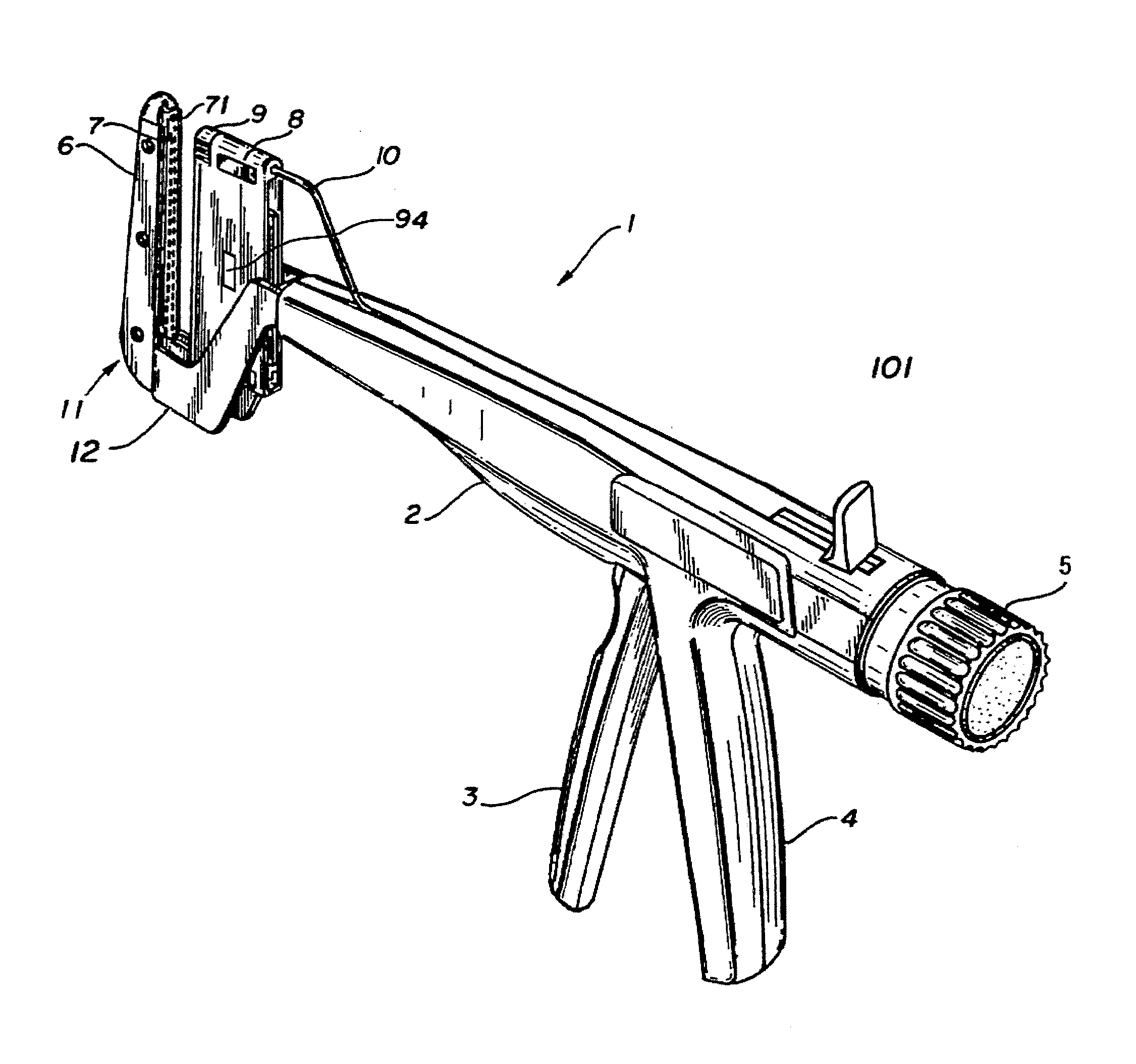
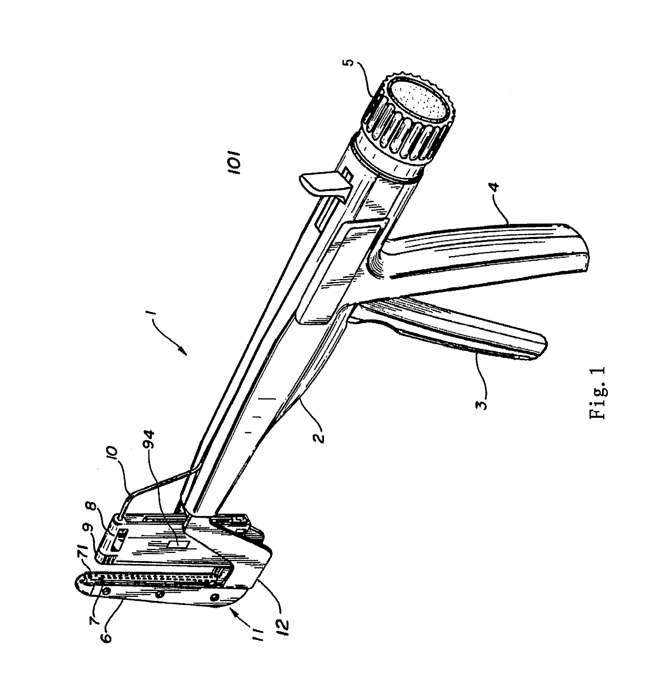
[0038]FIG. 1 shows the perspective view of a stapler 1 according to the present invention. The stapler 1 comprises a support base 2 having a proximal end and a distal end, an end effector 11 located at the distal end of the support base 2, a trigger 3 and a handle 4 both located at a proximal side of the support base 2, and a knob 5 located at the proxima...


PUM

PropertyMeasurementUnit
coloraaaaaaaaaa
strengthaaaaaaaaaa
dimensionaaaaaaaaaa

Abstract

A linear stapler comprises a support base having a proximal end and a distal end; a trigger located at the proximal end of the support base; an end effector located at the distal end of the support base, fired by the trigger and including a cartridge. The cartridge comprises a cartridge body. The cartridge body includes staple slots for accommodating staples; and a cartridge lockout which is forced into an open position to abut against an outer side of a staple driver when the cartridge is not fired and which springs back toward the inside direction of the cartridge body after the staples in the cartridge are fired by the staple driver. Another linear stapler comprises a support base having a proximal end and a distal end; a trigger located at the proximal end of the support base; an end effector located at the distal end of the support base, fired by the trigger and including a cartridge, the cartridge comprising a cartridge body including a spent cartridge indicator.

Description

TECHNICAL FIELD[0001]The present invention relates to a surgical stapling and cutting instrument. More specifically, the present invention relates to a linear stapler incorporating a cartridge with a lockout which can prevent a used or spent cartridge from refiring. The present invention also relates to a linear stapler incorporating a cartridge with a spent cartridge indicator which can indicate a spent cartridge.BACKGROUND OF THE INVENTION[0002]Surgical stapling and cutting instruments have been used in the prior art to simultaneously make an incision in tissue and apply lines of staples on opposing sides of the incision. End effectors of such instruments commonly include a pair of cooperating jaw members that, if the instrument is intended for endoscopic or laparoscopic applications, are capable of passing through a cannula passageway. One of the jaw members generally receives a staple cartridge having at least two laterally spaced rows of staples. The other jaw member defines an...

Claims


Application Information

Patent Timeline
Patent Type & Authority Applications(United States)
IPC IPC(8): A61B17/068
CPCA61B17/072A61B17/068A61B2019/4873A61B2017/07271A61B2090/0814
Inventor NALAGATLA, ANIL K.
Owner CILAG GMBH INT
Why Eureka
Try Eureka