

Magnetic head, magnetic recording method and apparatus for controlling magnetic head with spin torque oscillator in a disk drive
a magnetic recording method and magnetic recording technology, applied in the field of magnetic recording methods and apparatuses for controlling the magnetic head with spin torque oscillator in the disk drive, can solve the problems of reducing the anisotropic energy that would maintain the magnetization state, the recorded magnetization state is more readily disturbed by thermal fluctuation, and the practical limit of simply extending current technology, etc., to achieve the effect of reducing the curvature of the recording edge, reducing the blurring or the curvatur
- Summary
- Abstract
- Description
- Claims
- Application Information
AI Technical Summary
Benefits of technology
Problems solved by technology
Method used
Image

Examples
first embodiment
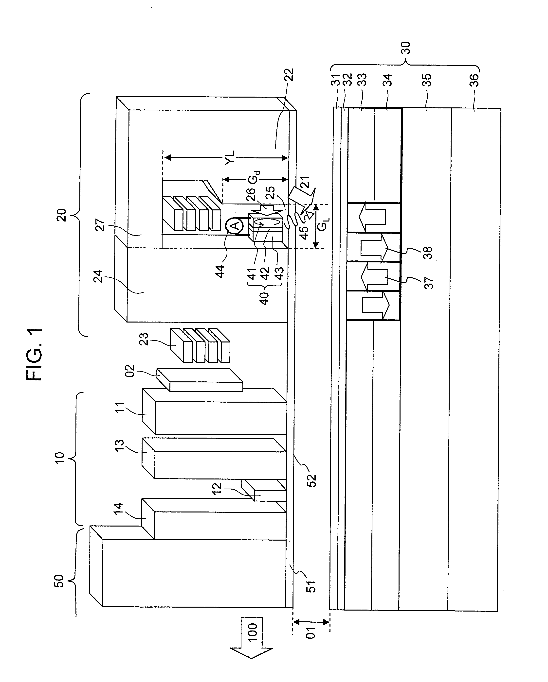
[0089]FIG. 1 is a schematic diagram of a perpendicular magnetic recording medium and a magnetic head according to an embodiment.
(Perpendicular Magnetic Recording Medium)
[0090]A perpendicular magnetic recording medium 30 includes a super-smooth and heat-resistant non-magnetic substrate 36 of glass, Si, plastics, or NiP plated Al, for example. The perpendicular magnetic recording medium 30 further includes, disposed on the substrate 36, a soft-magnetic underlayer 35 of FeCoTaZr and the like; first and second recording layers 34 and 33 of a magnetic film containing CoCrPt, a L12-Co3Pt base alloy, a L12-(CoCr)3Pt base alloy, a L11-Co50Pt50 base alloy, a m-D019 type Co80Pt20 base alloy, CoCrSiO2 / Pt, a CoB / Pd magnetic super-lattice, or L10 type FePt as a major constituent element, and an additive such as SiO2, TiO2, C, B, Ag, Cu, Au, Ni, Fe, Cr, Mn, or Pd which may be added as needed; an overcoat layer 32 of C or FCAC (Filtered Cathodic Arc Carbon), for example; and a lubricant layer 31, ...
second embodiment
[0119]In the present embodiment, a detailed example of the magnetic head according to the first embodiment will be described.
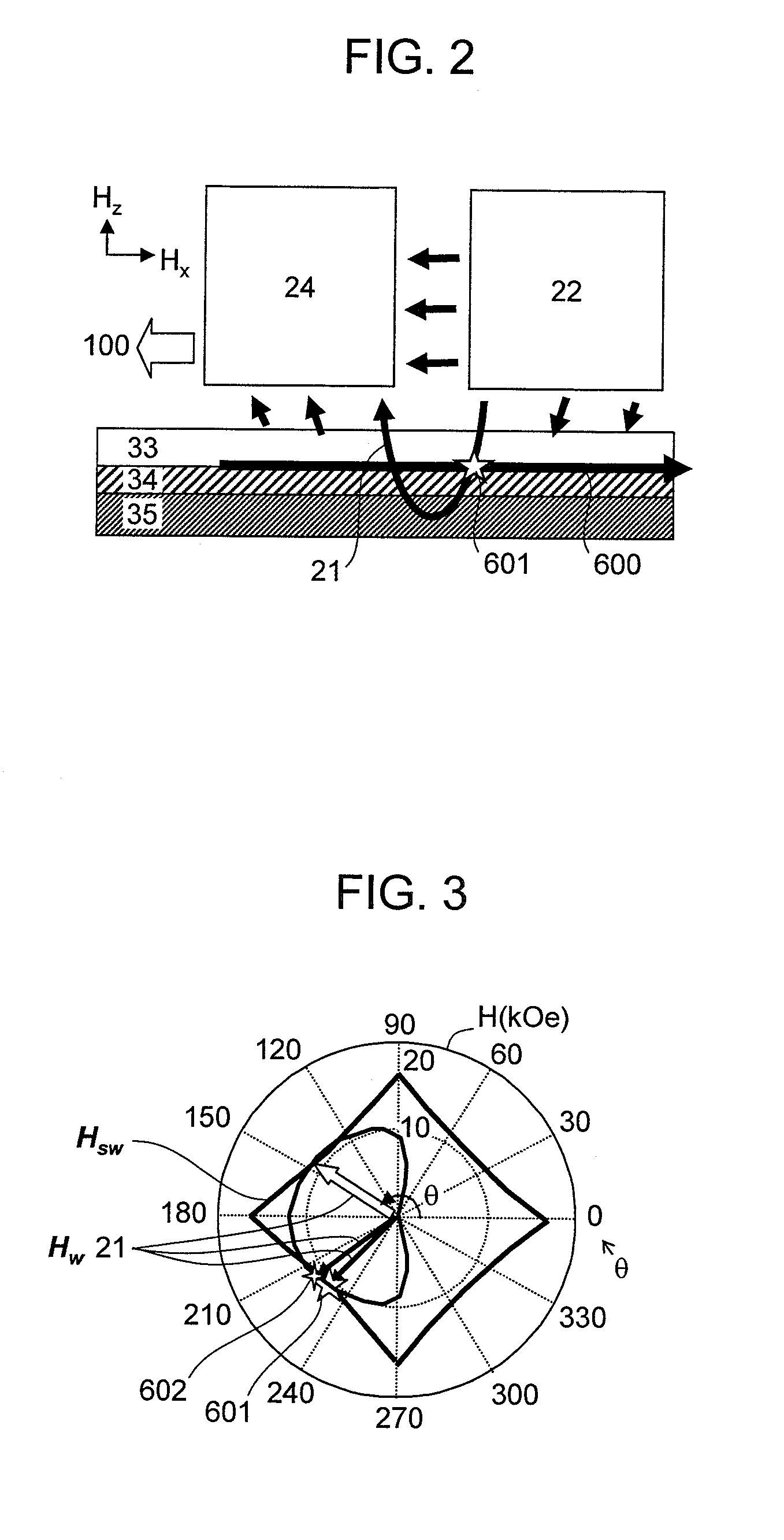
[0120]As described in the Summary with reference to FIG. 38, in the conventional magnetic head, the magnetization of the perpendicular magnetic recording medium is reversed immediately under the main magnetic pole, particularly in a region in the vicinity of the side of the main magnetic pole that is under the strong influence of the demagnetization of the field perpendicular magnetic recording medium such that recording takes place even only with the magnetic field from the main magnetic pole. As a result, the recorded track width is determined by the magnetic field width from the main magnetic pole, and desired narrow track magnetic recording cannot be performed even by microwave assisted magnetic recording. Thus, according to the present embodiment, attention is focused on important parameters of the perpendicular magnetic recording medium, such as the crys...
third embodiment
[0154]According to the present embodiment, another magnetic head that provides a particularly strong high-frequency oscillation magnetic field will be described.
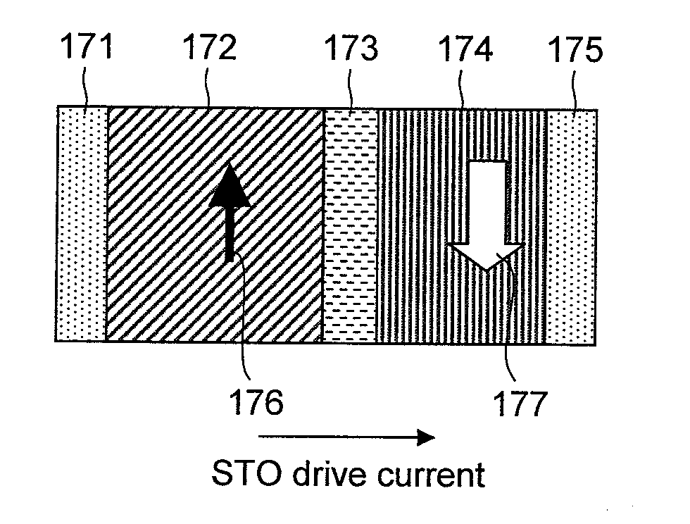
[0155]In order to generate a strong high-frequency magnetic field, it is preferable to increase particularly the saturation magnetic flux density and the film thickness while suppressing the development of a magnetic domain structure in the FGL. The present inventors conducted studies and have found that, as illustrated in FIG. 16, the development of the magnetic domain structure can be suppressed by layering the first and second FGLs 162 and 164 of a magnetic alloy with negative perpendicular magnetic anisotropy energy, such as Fe0.4CO0.6, Fe0.01Co0.99, or Co0.8Ir0.2; a Heusler alloy such as CoFeGe, CoMnGe, CoFeAl, CoFeSi, or CoMnSi; or a magnetic super-lattice such as Co / Fe, Co / Ir, Co / Ni, or CoFeGe / CoMnGe, in which the demagnetization field is also taken into consideration such that the magnetization tends to be oriented i...
PUM
| Property | Measurement | Unit |
|---|---|---|
| gap length | aaaaa | aaaaa |
| gap depth | aaaaa | aaaaa |
| gap depth | aaaaa | aaaaa |
Abstract
Description
Claims
Application Information