Braking apparatus

Active Publication Date: 2013-09-12
KONE CORP
View PDF7 Cites 7 Cited by
  • Summary
  • Abstract
  • Description
  • Claims
  • Application Information

AI Technical Summary

Benefits of technology

[0014]In an implementation with a first brake comprising a first electromagnet and a second brake comprising a second electromagnet, a first interrupting device is fitted to interrupt the magnetizing current to the first electromagnet but not to the second electromagnet and a second interrupting device is fitted to interrupt the magnetizing current to the second electromagnet but not to the first electromagnet. Such a solution enables the supply of current to the electromagnets of different brakes to be interrupted independently of the other brake, and therefore each one of the brakes can also be activated separately. This solution allows the operational condition of each brake to be tested alternately by releasing one of the brake

Problems solved by technology

Therefore, failure of the first or the second control element, and likewise failure of the first or the second interrupting device or failure of the first or the second electromagnet will not prevent activation of the brake, so the braking apparatus of the invention

Method used


Image

  • Braking apparatus
  • Braking apparatus
  • Braking apparatus

Examples


Embodiment Construction

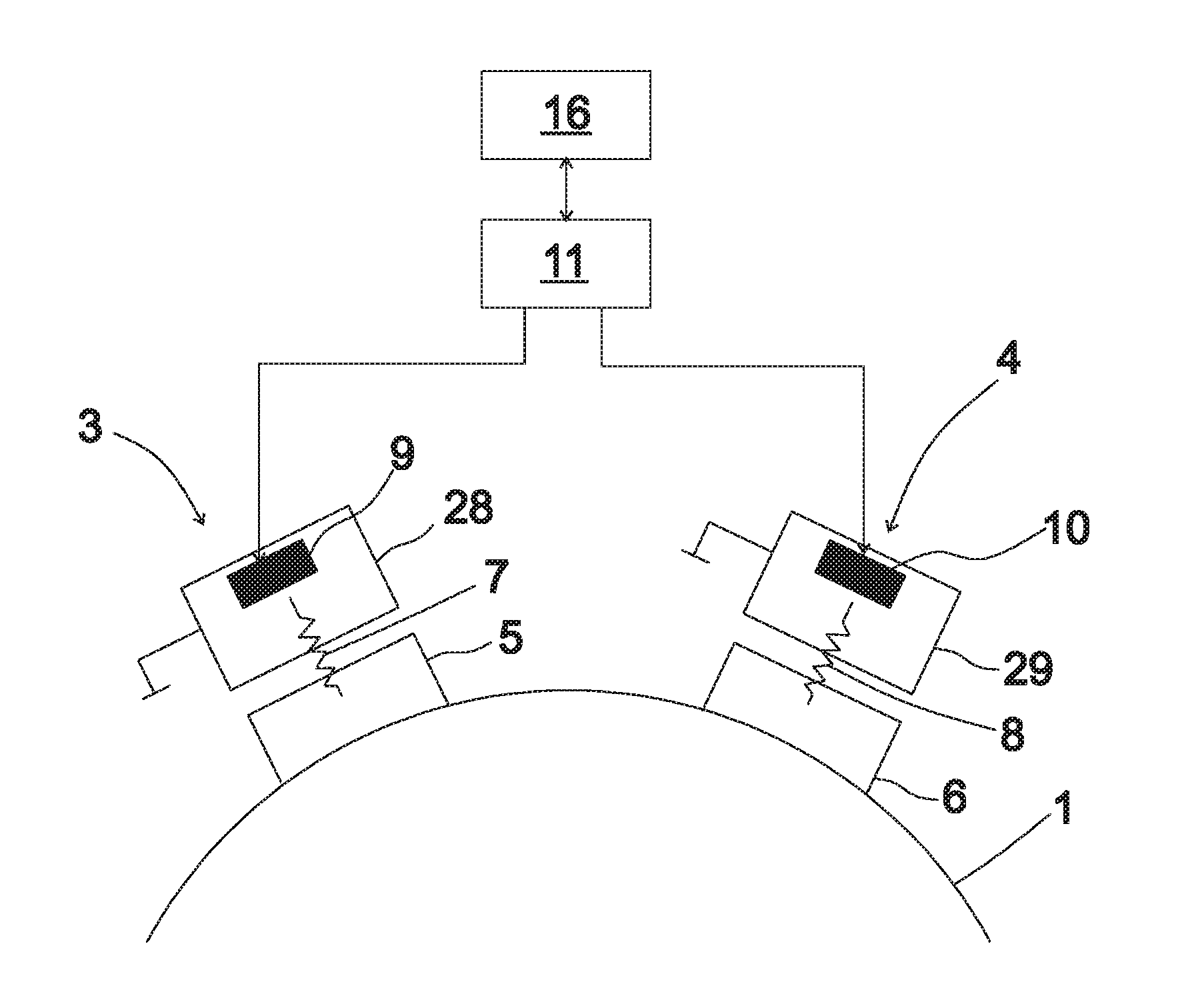
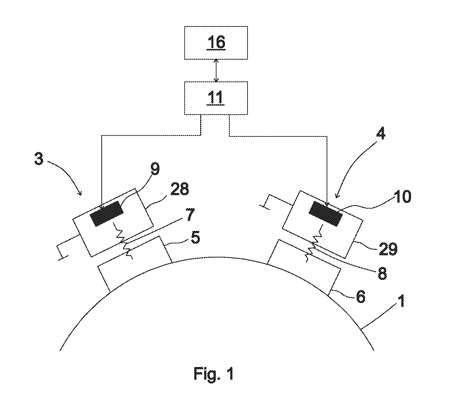
[0021]FIG. 1 shows a block diagram representing a braking apparatus according to the invention for an elevator hoisting machine. The rotating part 1 of the elevator hoisting machine comprises a traction sheave with rope grooves for the suspension ropes (not shown in FIG. 1) of the elevator car. The force effect produced by the hoisting machine is transmitted via the suspension ropes to the elevator car as a force moving / supporting the elevator car. The braking apparatus of the hoisting machine comprises two separate brakes 3, 4, the frame parts 28, 29 of both brakes being secured to a stationary part 2 of the same hoisting machine. Each brake has a brake shoe 5, 6 movably attached to the stationary part 28, 29 of the brake by means of spring plates 7,8. The spring plates 7, 8 are push springs and they apply to the brake shoe 5, 6 a force that pushes the brake shoe 5, 6 forwards toward the braking surface of rotating part 1 of the hoisting machine. The brake 3, 4 is in an activated s...


PUM


Abstract

A braking apparatus is provided for braking the rotating part of a hoisting machine. The braking apparatus includes one or more brakes, which contain altogether at least one movable brake shoe, spring elements for activating the brake by moving the brake shoe forward, at least two electromagnets, which, when magnetized by a magnetizing current, apply a force of attraction to bodies conducting magnetic flux. The electromagnets are fitted to release the brake by pulling the brake shoe backwards by resisting the spring elements. The brake is fitted to be activated by reducing the magnetizing current of the electromagnet. The braking apparatus includes a power supply circuit for the electromagnets, which contains controllable power supply interrupting devices. The electromagnets are connected to the power supply circuit in such a way that the supply of magnetizing current to each electromagnet can be interrupted by means of at least two different interrupting devices.

Description

FIELD OF THE INVENTION [0001]The invention relates to braking apparatus for hoisting machines.BACKGROUND OF THE INVENTION[0002]The braking device generally used e.g. in an elevator hoisting machine is a machine brake which mechanically engages a rotating part of the hoisting machine. The machine brake may be constructed e.g. as a drum brake or a disc brake. The braking function of the machine brake is activated when the supply of power to the electromagnet of the brake is interrupted e.g. by means of a relay or contactor. The relay / contactor which interrupts the supply of power to the electromagnet of the brake is usually of a type that only remains in the conducting state for as long as power is being supplied to the control terminal of the relay / contactor. Supply of power to the control terminal takes place via the elevator safety circuit and is interrupted when the safety circuit is opened. When the brake is activated, a brake shoe is pressed mechanically against a braking surfac...

Claims


Application Information

Patent Timeline
IPC IPC(8): F16D63/00F16D49/00
CPCH02P3/04F16D63/002F16D49/00H02P15/00B66B1/32B66B5/00
Inventor KATTAINEN, ARI
Owner KONE CORP
Why Eureka
Try Eureka