Wind turbine generator, method of controlling the same, and wind turbine generating system

a technology of wind turbine generator and generating system, which is applied in the direction of machines/engines, process and machine control, instruments, etc., can solve the problems of electric device temperature sometimes dropping to a temperature, warranty of manufacturers, damage to electric devices, etc., and achieve the effect of preventing damage to electric devices and damage to power supply units

Active Publication Date: 2011-03-31
MITSUBISHI HEAVY IND LTD
View PDF22 Cites 6 Cited by
  • Summary
  • Abstract
  • Description
  • Claims
  • Application Information

AI Technical Summary

Benefits of technology

[0006]The present invention has been achieved to solve the above problem, and an object thereof is to provide a wind turbine generator that prevents a damage on electric devices when installed in a cold weather, a method of controlling the same, and a wind turbine generating system.
[0010]With the configuration, in the case where the voltage of the utility grid drops due to occurrence of power outage or the like in a state where the temperature of the power supply unit is equal to or lower than the function guarantee temperature of the power supply unit, the power supply unit can be disconnected from the utility grid. As a result, in such a state where the power supply unit is equal to or lower than the function guarantee temperature, voltage application to the power supply unit caused by recovery of the utility grid can be prevented, and a damage on the power supply unit caused by voltage application at a temperature out of the function guarantee temperature can be prevented.
[0021]For example, in a case where power outage or the like occurs in the utility grid and power supply from the utility grid to the switch gear is interrupted, power is supplied from the electric storage device to other devices, and the control of opening / closing the switch gear is performed. Therefore, before the remaining capacity of the electric storage device drops below the charge amount necessary to perform control of opening / closing the switch gear, determination to set the switch gear to the open state has to be made. Therefore, by setting the predetermined period based on the remaining capacity of the electric storage device as described above, an instruction to open the switch gear is outputted while the charge amount for controlling the switch gear is secured in the electric storage device. Consequently, by power supply from the electric storage device, the connection between the power supply unit and the utility grid can be reliably interrupted.
[0024]Consequently, in the case where the voltage of the utility grid drops due to occurrence of power outage or the like in the state where the temperature of the power supply unit is equal to or lower than the function guarantee temperature of the power supply unit, the power supply unit can be disconnected from the utility grid. As a result, for example, in a state where the power supply unit is equal to or lower than the function guarantee temperature, voltage application to the power supply unit caused by recovery of the utility grid can be prevented, and a damage on the power supply unit caused by voltage application at a temperature out of the function guarantee temperature can be prevented.
[0027]Accordingly, in a case where the voltage of the utility grid drops due to occurrence of power outage or the like in a state where the temperature of the power supply unit is equal to or lower than the function guarantee temperature of the power supply unit, the power supply unit can be disconnected from the utility grid. As a result, for example, in the state where the temperature of the power supply unit is equal to or less than the function guarantee temperature, voltage application to the power supply unit caused by recovery of the utility grid can be prevented, and a damage on the power supply unit caused by voltage application at a temperature out of the function guarantee temperature can be prevented.
[0028]According to the present invention, there is exerted an effect that a damage on electric devices is prevented in a wind turbine generator installed in a cold weather.

Problems solved by technology

However, hitherto, in such a cold weather, even when a heater or the like is operating, as the outside air temperature decreases, the temperatures of electric devices sometimes decrease to a temperature (for example, −25 degrees) out of the warranty of manufacturers thereof.
Accordingly, there is caused a problem that the electric devices are damaged.
Since the electric devices are damaged, there occurs another problem that the operation rate of the wind turbine generator decreases.

Method used


Image

  • Wind turbine generator, method of controlling the same, and wind turbine generating system
  • Wind turbine generator, method of controlling the same, and wind turbine generating system
  • Wind turbine generator, method of controlling the same, and wind turbine generating system

Examples


first embodiment

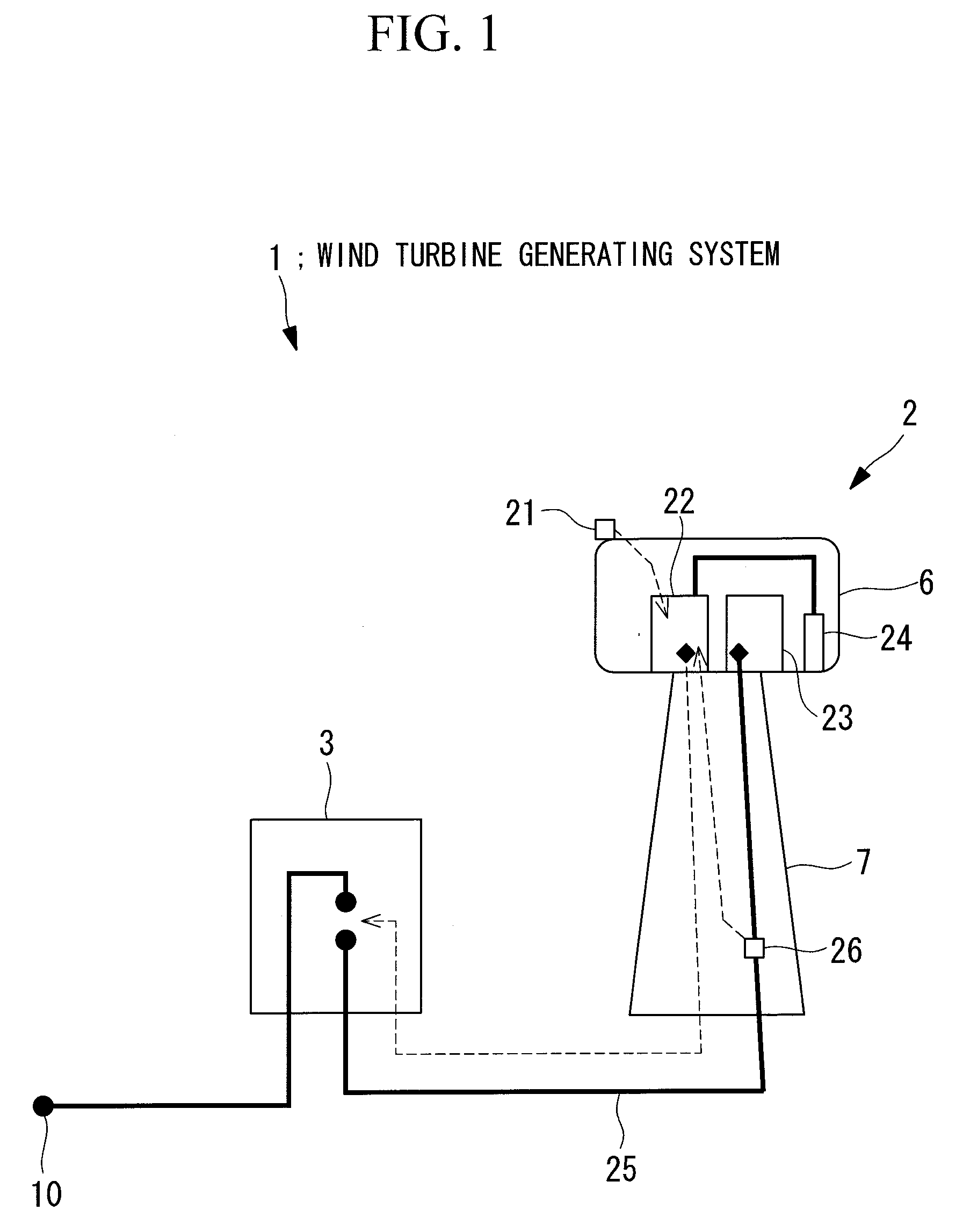
[0044]FIG. 1 is a diagram showing a configuration of an entire wind turbine generating system 1 according to a first embodiment of the present invention. The wind turbine generating system 1 includes a wind turbine generator 2 and a switch gear 3. The wind turbine generator 2 is connected to the switch gear 3 via a power supply line 25, and further, the switch gear 3 and a utility grid 10 are connected to each other via a not-shown transformer.

[0045]The switch gear 3 switches between connection and disconnection of the wind turbine generator 2 and the utility grid 10. In a case where the switch gear 3 is in a close state, the wind turbine generator 2 and the utility grid 10 are in a connection state. In an open state, the wind turbine generator 2 and the utility grid 10 are in a non-connection state.

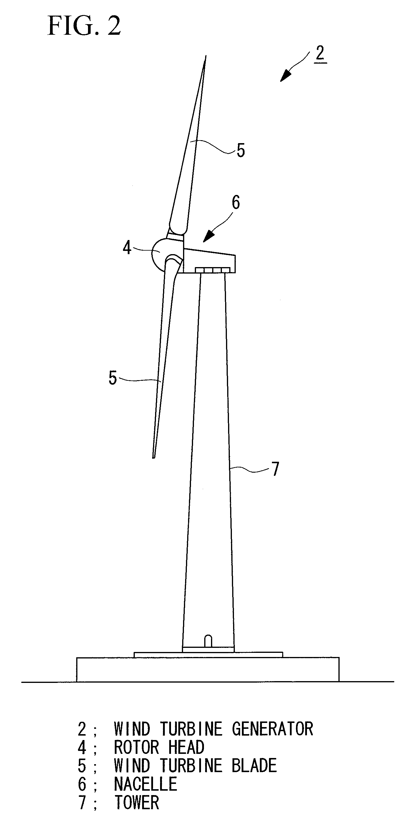
[0046]FIG. 2 is a diagram showing a schematic configuration of the wind turbine generator 2 according to the present embodiment.

[0047]The wind turbine generator 2 includes, as shown in F...

second embodiment

[0073]Described next are a wind turbine generator 2, a method of controlling the same, and a wind turbine generating system according to a second embodiment of the present invention.

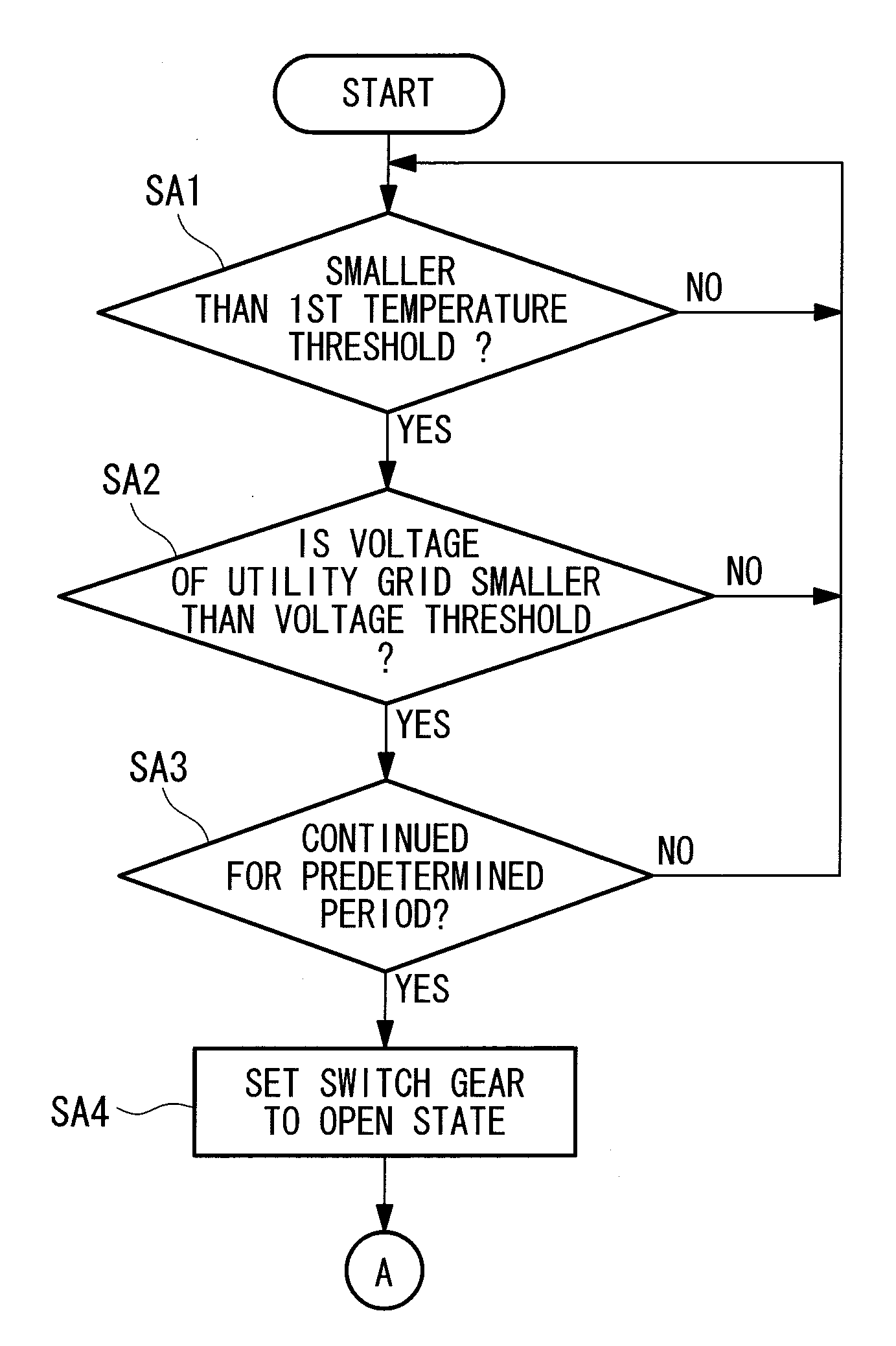
[0074]The wind turbine generating system 1 according to the present embodiment has a configuration similar to that of the foregoing first embodiment but there are differences in a method and processes of determining control to open / close the switch gear 3 by the control unit 22. Concretely, in the foregoing first embodiment; the ambient temperature of the power supply unit 23 is estimated from the outside air temperature, and the estimated ambient temperature and the first temperature threshold are compared with each other. In the present embodiment, by comparing the outside air temperature directly with the first temperature threshold, open / close control of the switch gear 3 is determined.

[0075]In the following, processes of determining the open / close state of the switch gear 3 to be executed by the con...


PUM


Abstract

Damage is prevented on electric devices in a case where a generator is installed in a cold weather. A wind turbine generator includes a power supply unit connected to a utility grid via a switch gear; a utility grid voltage measuring unit provided between the power supply unit and the utility grid, for measuring a voltage of the utility grid; and a temperature measuring unit for obtaining an ambient temperature of the power supply unit. In a case where a measurement value of the temperature measuring unit or an ambient temperature of the power supply unit estimated based on the measurement value is smaller than a first temperature threshold determined based on a function guarantee temperature of the power supply unit and the voltage measured by the utility grid voltage measuring unit is smaller than a preset voltage threshold, the switch gear operates to interrupt the connection between the power supply unit and the utility grid.

Description

TECHNICAL FIELD[0001]The present invention relates to a wind turbine generator, a method of controlling the same, and a wind turbine generating system.BACKGROUND ART[0002]Conventionally, there is known a wind turbine generator for generating power by using wind power as natural energy. In some cases, such a wind turbine generator is installed in a cold weather where the outside air temperature is as low as −40° C. In such a Cold weather, as the outside air temperature decreases, accordingly decreased are the temperatures of electric devices provided in a nacelle of the wind turbine generator. As a countermeasure, there is proposed a method of maintaining the electric devices in the nacelle at a predetermined temperature by using a heater or the like, thereby compensating the operations.[0003]Patent Citation 1: Japanese Unexamined Patent Application, Publication No. 2003-288832DISCLOSURE OF INVENTION[0004]However, hitherto, in such a cold weather, even when a heater or the like is op...

Claims


Application Information

Patent Timeline
Patent Type & Authority Applications(United States)
IPC IPC(8): G06F1/26
CPCF03D7/0284F03D9/003F03D11/0091F05B2260/821F05B2270/107Y02E10/723F05B2270/325F05B2270/337H02P29/0088Y02E10/722F05B2270/303F03D17/00F03D9/255H02P29/68Y02E10/72
Inventor YASUGI, AKIRA
Owner MITSUBISHI HEAVY IND LTD
Why Eureka
Try Eureka