Control drive circuit for electric power tool

Inactive Publication Date: 2007-08-30
MATSUSHITA ELECTRIC WORKS LTD
View PDF22 Cites 5 Cited by
  • Summary
  • Abstract
  • Description
  • Claims
  • Application Information

AI Technical Summary

Benefits of technology

[0021]In accordance with the aspects of the present invention, there is provided either the circuit switch provided at the power supply sides of the drive circuits for driving the switching elements or a forcible turn-off unit for forcibly turning off the switching elements, so that the punch-through current does not flow through the switching elements when the supply of the electric power is interrupted, and thus the switching elements are not destroyed by the punch-through current.

Problems solved by technology

The same problem occurs in the switching elements of other phases.

Method used


Image

  • Control drive circuit for electric power tool
  • Control drive circuit for electric power tool
  • Control drive circuit for electric power tool

Examples


Embodiment Construction

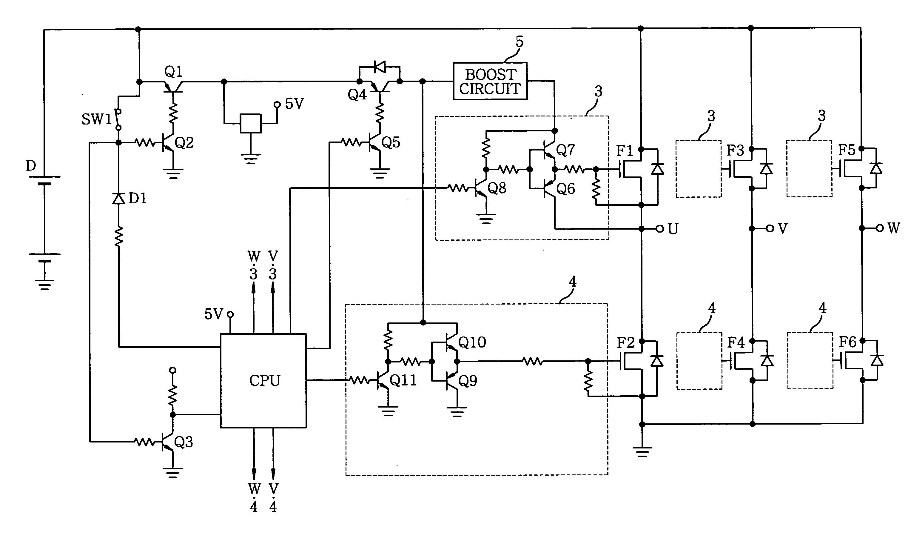
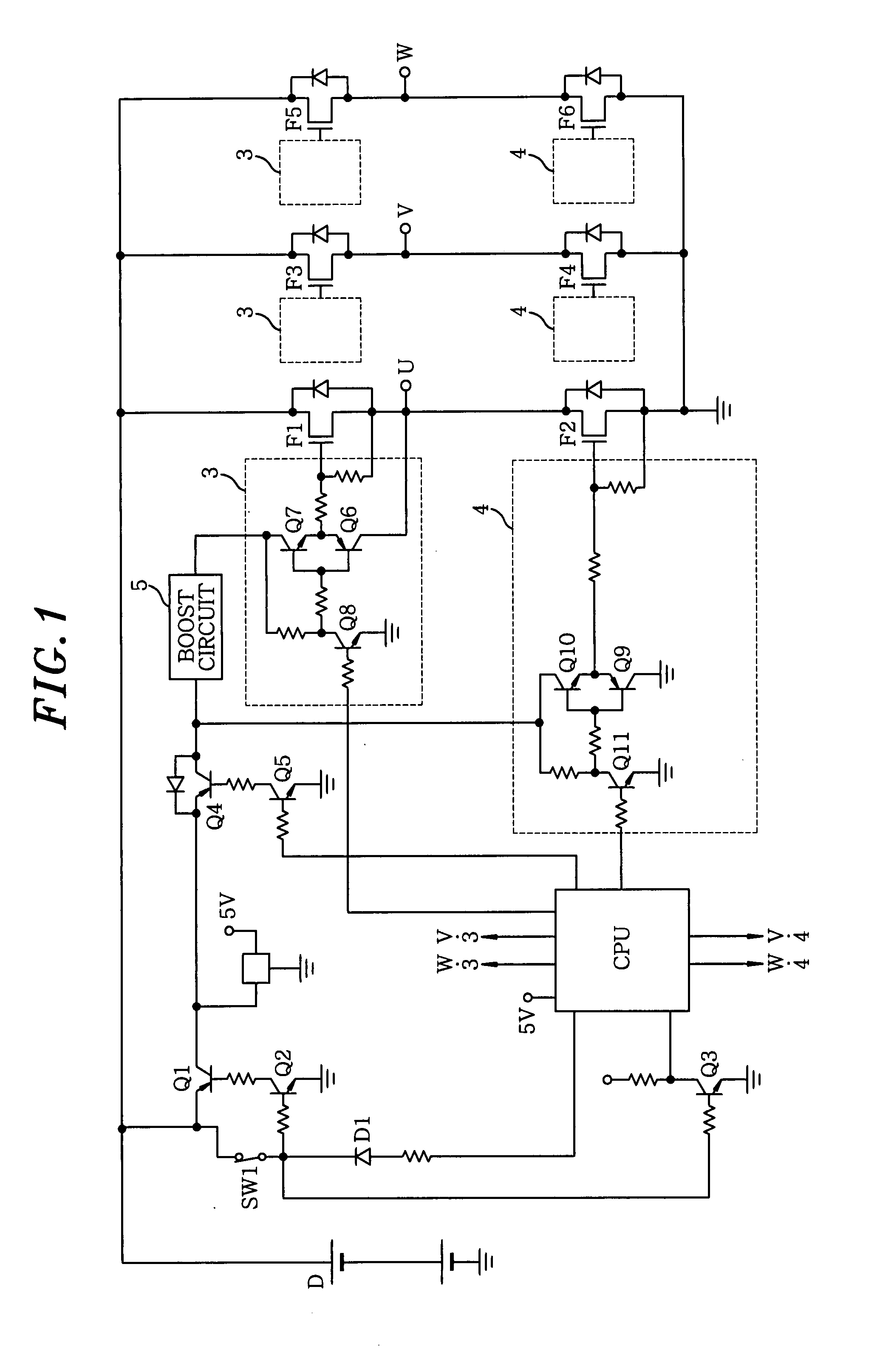
[0026]Hereinafter, the present invention will be explained based on embodiments illustrated in the accompanying drawings. FIG. 1 is a circuit diagram showing a control drive circuit in accordance with an embodiment of the present invention. Since basic configuration thereof is the same as those of the conventional one shown in FIG. 3, a redundant description thereof will be omitted. A circuit switch (transistor) Q4 is disposed on power supply sides of the drive circuits 3 and 4 for driving the bridge-structured switching elements F1 to F6. The circuit switch Q4 is turned on and off via a transistor Q5 according to an output of the control circuit CPU. When the circuit switch Q4 is turned off, the supply of the electric power to the drive circuits 3 and 4 is interrupted.

[0027]Further, when an electric power is supplied to the control circuit CPU by turning on the trigger switch SW1, the circuit switch Q4 is turned on by the output of the control circuit CPU. Thereafter, the drive cir...


PUM


Abstract

In a control drive circuit for an electric power tool, a bridge-structured motor, which has a bridge structure and includes switching elements and a motor body, is connected to a power supply unit without any mechanical contacts, and an electric power is supplied to a control circuit for controlling the switching elements by turning on a trigger switch. Further, a circuit switch is provided at power supply sides of drive circuits for driving the switching elements, the circuit switch being controlled by the control circuit to interrupt supply of the electric power to the drive circuits.

Description

FIELD OF THE INVENTION[0001]The present invention relates to a control drive circuit for an electric power tool.BACKGROUND OF THE INVENTION[0002]As for an electric power tool in which a motor is used as an electric power source and a secondary battery is used as a power supply unit, there are provided various types of control drive circuits for driving the motor. (see, Japanese Patent Laid-open Application No. 2005-137087 (hereinafter, referred to as “Patent Reference 1”)).[0003]In recently provided control drive circuits, mechanical contacts are removed from circuits between a power supply unit and a motor in order to improve vibration-resistance and durability, while an electric power is supplied to a control circuit in response to the ‘ON’ operation of a trigger switch and the supply of the power thereto is interrupted when a trigger switch is turned off in order to avoid the unnecessary consumption of a secondary battery.[0004]An example of the above-described control drive circ...

Claims


Application Information

Patent Timeline
Patent Type & Authority Applications(United States)
IPC IPC(8): H02P7/06
CPCH02M1/08H02M2001/0006H03K17/6877H03K17/6871H03K17/08122H02M1/0006
Inventor MIYAZAKI, HIROSHIKAWAI, AKIRA
Owner MATSUSHITA ELECTRIC WORKS LTD
Why Eureka
Try Eureka