Diversity receiving device
a receiving device and diversity technology, applied in transmission monitoring, power management, high-level techniques, etc., can solve the problem of significant power consumption of high frequency, and achieve the effect of reducing overall power consumption without degrading reception performan
- Summary
- Abstract
- Description
- Claims
- Application Information
AI Technical Summary
Benefits of technology
Problems solved by technology
Method used
Image
Examples
first embodiment
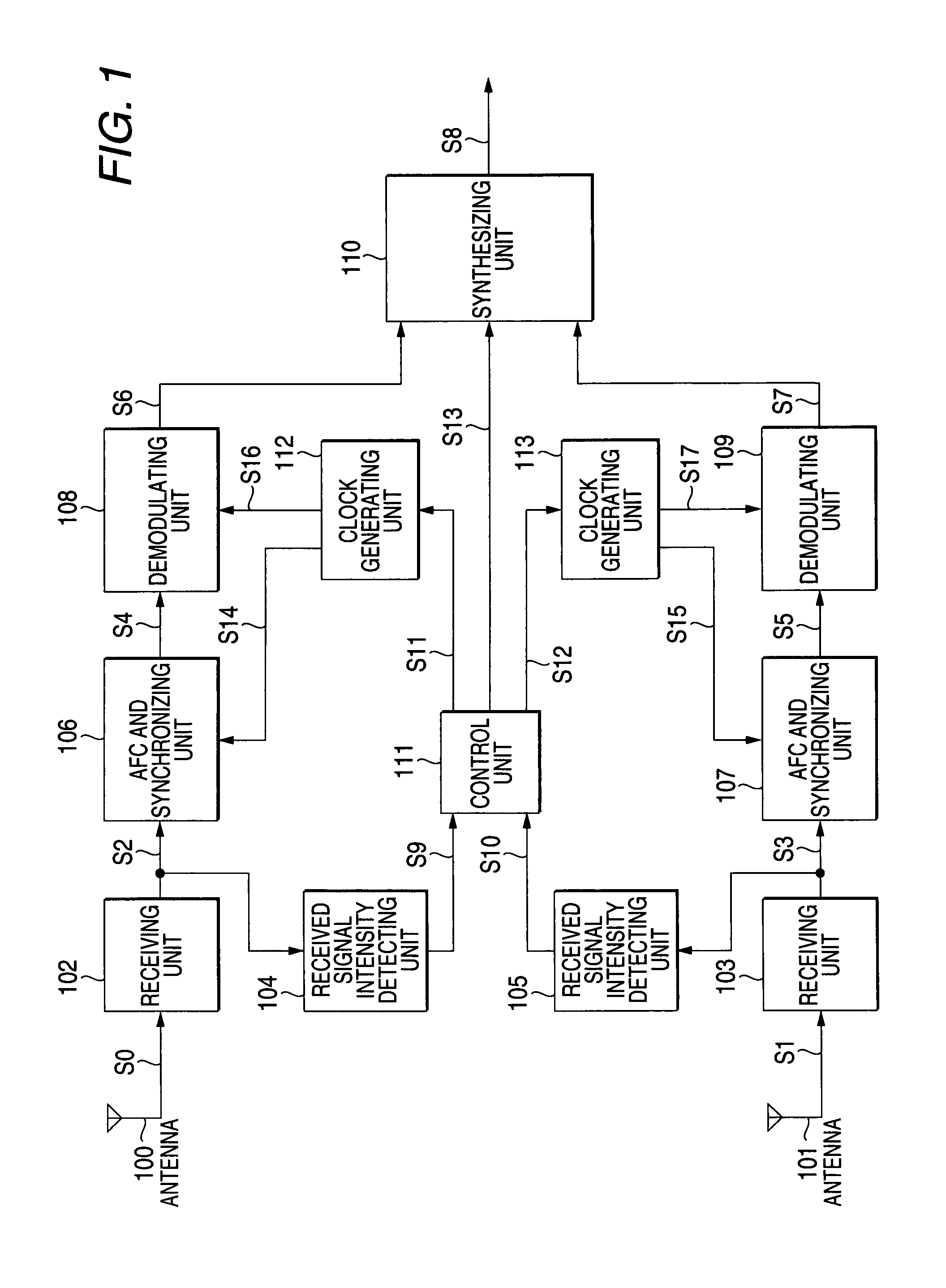
[0036]FIG. 1 is a block diagram showing the configuration of a diversity receiving device according to a first embodiment of the invention. In FIG. 1, reference numeral 100 denotes a first antenna, reference numeral 101 denotes a second antenna, reference numeral 102 denotes a receiving unit of a first system, reference numeral 103 denotes a receiving unit of a second system, reference numeral 104 denotes a received signal intensity detecting unit of the first system, reference numeral 105 denotes a received signal intensity detecting unit of the second system, reference numeral 106 denotes an AFC and synchronizing unit of the first system, reference numeral 107 denotes an AFC and synchronizing unit of the second system, reference numeral 108 denotes a demodulating unit of the first system, reference numeral 109 denotes a demodulating unit of the second system, reference numeral 110 denotes a synthesizing unit, reference numeral 111 denotes a control unit, reference numeral 112 deno...
second embodiment
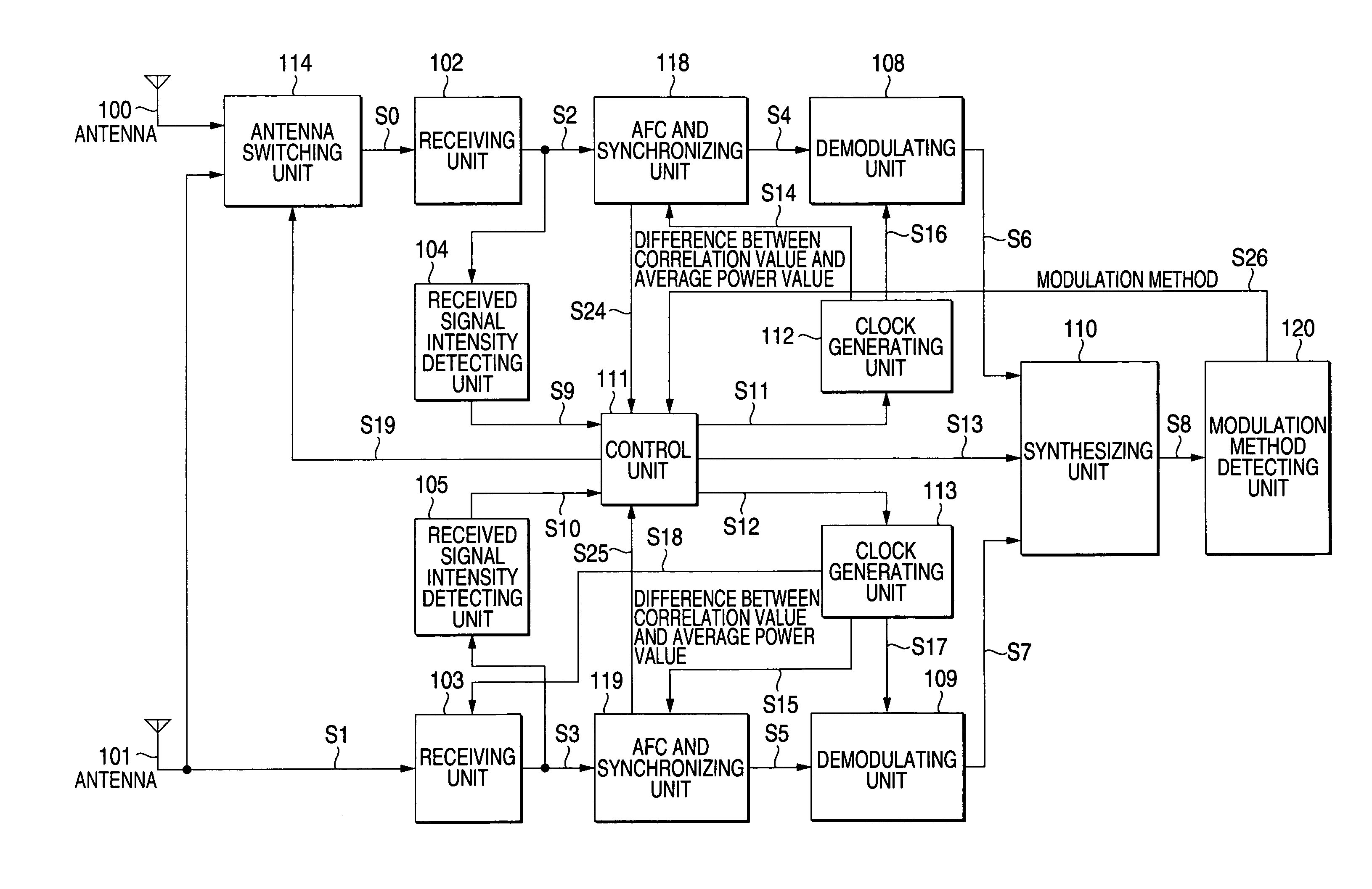
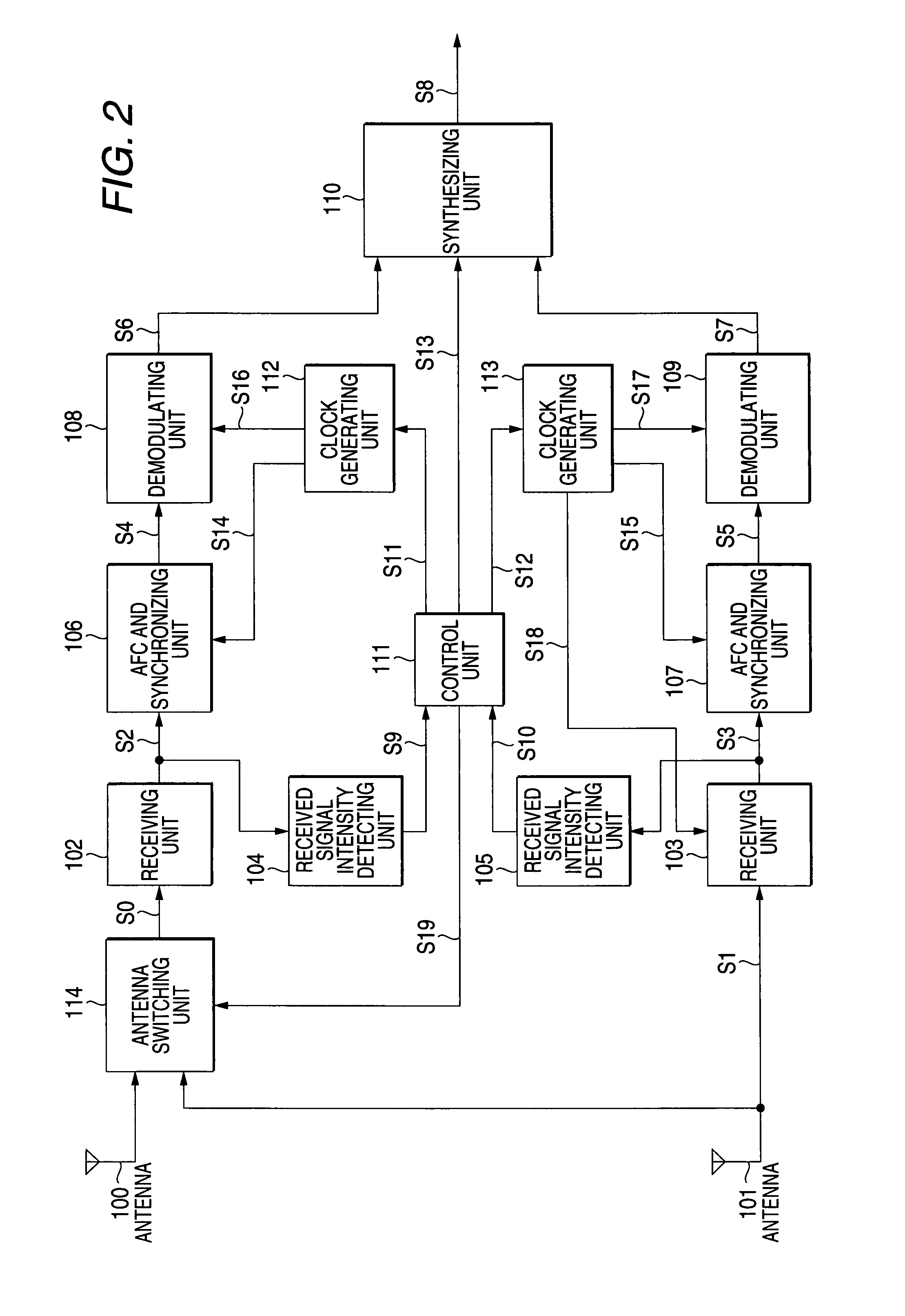
[0054]FIG. 2 is a block diagram showing the configuration of a diversity receiving device according to a second embodiment of the invention. In FIG. 2, an antenna switching unit 114 is added to the configuration of the first embodiment shown in FIG. 1. Hereinafter, a difference from the first embodiment will be described.
[0055]The antenna switching unit 114 selects one of signals coming into two of the antennas 100 and 101 on the basis of an antenna selection signal S19, and outputs the signal as a received signal S0 to the receiving unit 102. A diversity method using such an antenna switching unit is referred to as an antenna selection synthesis diversity.
[0056]The control unit 111 receives the reception intensity detection signals S9 and S10 and outputs clock interruption control signals S11 and S12 according to the reception intensity detection signals S9 and S10. Further, the control unit 111 outputs a synthesis pattern selection signal S13 for selecting a synthesis pattern and ...
third embodiment
[0069]FIG. 3 is a block diagram showing the configuration of a diversity receiving device according to a third embodiment of the invention. In FIG. 3, reference numeral 100 denotes a first antenna, reference numeral 101 denotes a second antenna, reference numeral 102 denotes a receiving unit of a first system, reference numeral 103 denotes a receiving unit of a second system, reference numeral 104 denotes a received signal intensity detecting unit of the first system, reference numerals 105 denotes a received signal intensity detecting unit of the second system, reference numeral 115 denotes an AFC and synchronizing unit which performs time-division processing, reference numeral 116 denotes a demodulating unit which performs time-division processing, reference numeral 110 denotes a synthesizing unit, reference numeral 111 denotes a control unit, and reference numeral 117 denotes a clock generating unit. Here, two systems are exemplified as a plurality of systems.
[0070]The time-divis...
PUM
 Abstract
Description
Claims
Application Information
 - R&D
- Intellectual Property
- Life Sciences
- Materials
- Tech Scout
- Unparalleled Data Quality
- Higher Quality Content
- 60% Fewer Hallucinations
Browse by: Latest US Patents, China's latest patents, Technical Efficacy Thesaurus, Application Domain, Technology Topic, Popular Technical Reports.
© 2025 PatSnap. All rights reserved.Legal|Privacy policy|Modern Slavery Act Transparency Statement|Sitemap|About US| Contact US: help@patsnap.com


