Image-pickup apparatus having shutter apparatus

a technology of image-picking apparatus and shutter device, which is applied in the direction of shutters, instruments, optics, etc., can solve the problems of not revealing the optimum applied voltage, and achieve the effect of shortening the release time lag, speeding up the continuous shooting speed, and easily causing accuracy changes

Inactive Publication Date: 2013-09-26
CANON KK
View PDF4 Cites 4 Cited by
  • Summary
  • Abstract
  • Description
  • Claims
  • Application Information

AI Technical Summary

Benefits of technology

[0012]The present invention provides an image-pickup apparatus that does not require energizing to a trailing blade holding electromagnet in live view, can shorten a release time lag, and can speed up the continuous shooting spee

Problems solved by technology

However, Japanese Patent Laid-open No. 2009-31513 does not disclose an opti

Method used


Image

  • Image-pickup apparatus having shutter apparatus
  • Image-pickup apparatus having shutter apparatus
  • Image-pickup apparatus having shutter apparatus

Examples


embodiment 1

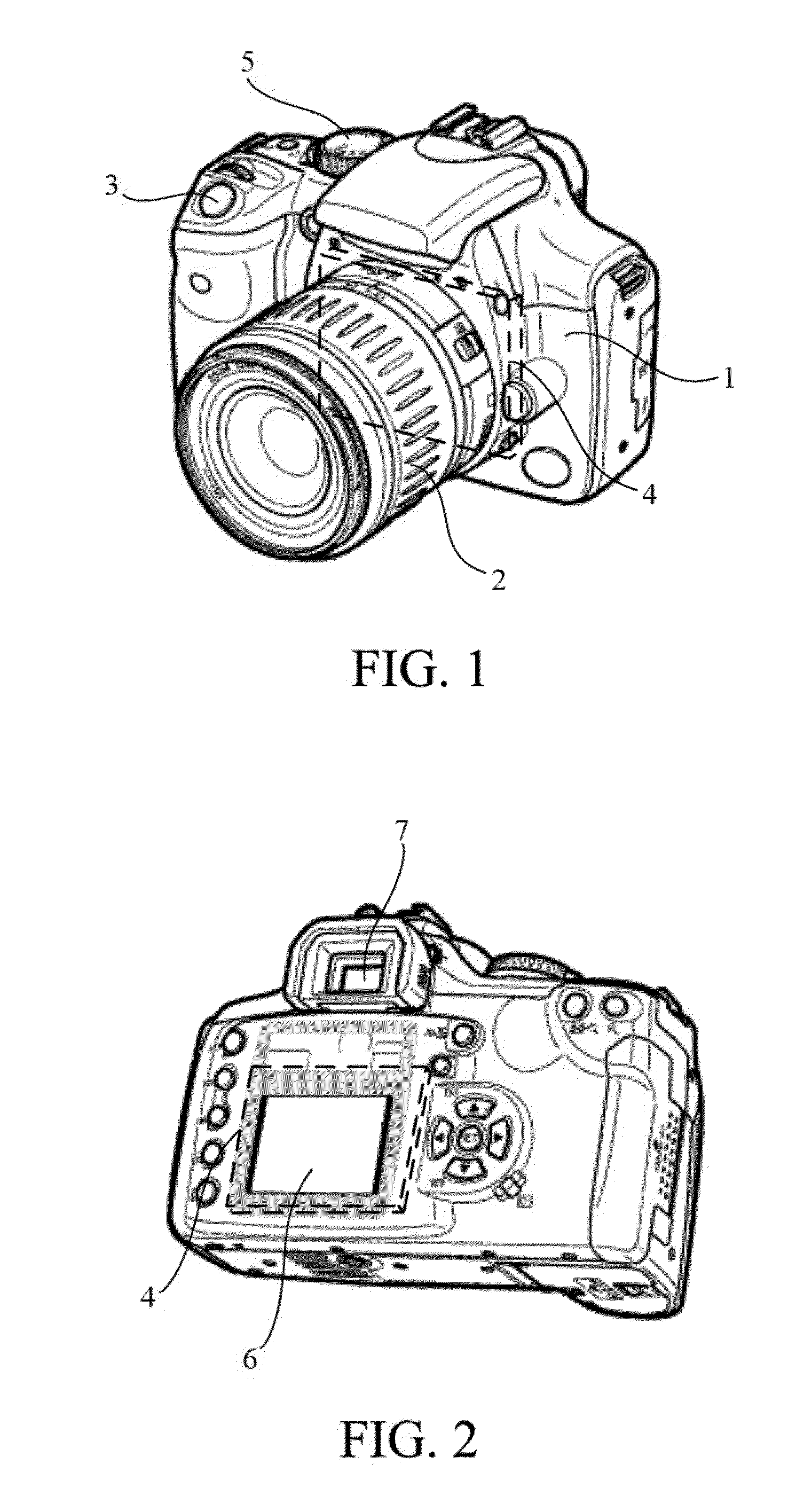
[0031]FIG. 1 illustrates a perspective view seen from diagonally forward of a digital single-lens reflex camera (image-pickup apparatus) that is Embodiment 1 of the present invention and FIG. 2 is a perspective view seen from diagonally backward of the digital single-lens reflex camera.

[0032]An image-pickup lens 2 is detachably attached to a digital single-lens reflex camera 1 (hereinafter, referred to as a “camera”). A release button 3 is a two-step switch so as to instruct the beginning of photometry and focus detection, and to instruct a shooting. A state lightly pressing the release button into a first step is called “Half-pressing”, and photometry and focus detection are performed in the state. A state further pressing from the “Half-pressing” into a second step is called “Full-pressing”, and a shutter apparatus 4 is driven and shooting is performed in the state. A mode dial switch 5 switches various shooting modes of the camera. Moreover, an image display 6 is used so as to co...

embodiment 2

[0097]Referring to FIGS. 13 and 14, an image-pickup apparatus that is the second embodiment of the present invention is described.

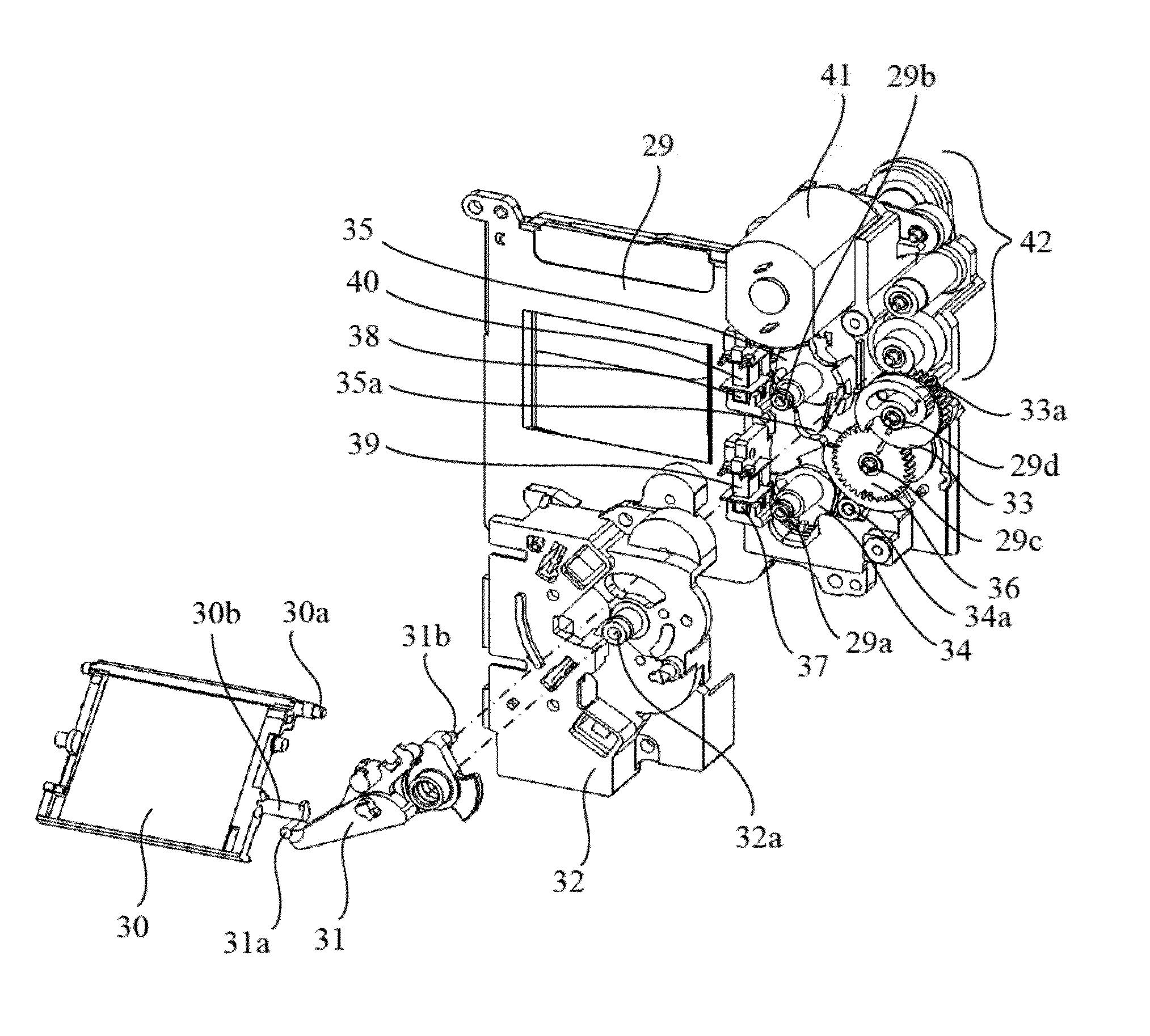
[0098]FIG. 13 is a plan view illustrating the charge operation completed state of the shutter apparatus provided in the image-pickup apparatus of the second embodiment is shown, and FIG. 14 is a cam diagram and a diagram of illustrating a motor voltage of the shutter apparatus provided in the image-pickup apparatus of the second embodiment.

[0099]The difference from the first embodiment is a shape of the leading blade second cam surface 36a2. The leading blade second cam surface 36a2 is within 296°-360° in the first embodiment, however, the leading blade second cam surface 36a2 is within 296°-311° in the second embodiment. Further, from FIG. 14, the charge operation on the leading blade second cam surface 36a2 ends before the beginning of the charge operation by the trailing blade second cam surface 36b2. The charge operation of the leading blade drive lev...


PUM


Abstract

An image-pickup apparatus includes a driving member for leading blades configured to drive a leading blade group, a driving member for trailing blades configured to drive a trailing blade group, a cam member configured to rotate the driving member for leading blades and the driving member for trailing blades, a motor configured to drive the cam member, and a controller configured to control the motor. The controller applies a second voltage that is lower than a first voltage applied in releasing the driving member for leading blades to the motor when the driving member for trailing blades is released at normal shooting, and a third voltage that is lower than the first voltage and that is higher than the second voltage to the motor when the driving member for trailing blades is released at live view shooting.

Description

BACKGROUND OF THE INVENTION[0001]1. Field of the Invention[0002]The present invention relates to an image-pickup apparatus such as a digital camera, and more particularly to an image-pickup apparatus having a shutter apparatus.[0003]2. Description of the Related Art[0004]A shutter apparatus has a leading blade group (hereinafter referred to as “leading blade”) that travels from a state in which an opening of a shutter closes (hereinafter referred to as “closed state”) to a state in which the opening opens (hereinafter referred to as “opened state”), and a trailing blade group (hereinafter referred to as “trailing blade”) that travels from the opened state to the closed state. Each of the leading and the trailing blades is configured by a plural of light shielding blades, and the light shielding blades are coupled by an arm so as to form a parallel link and are translated in a travelling direction.[0005]Some image-pickup apparatuses including the shutter apparatus have a live view fu...

Claims


Application Information

Patent Timeline
IPC IPC(8): G03B9/62
CPCG03B9/62G03B2217/007G03B19/12
Inventor SAKAI, MASANORI
Owner CANON KK
Why Eureka
Try Eureka