

Rotor unit, rotating electrical machine, and method of manufacturing rotor unit
- Summary
- Abstract
- Description
- Claims
- Application Information
AI Technical Summary
Benefits of technology
Problems solved by technology
Method used
Image

Examples
Embodiment Construction
[0023]Hereinafter, exemplary preferred embodiments of the present invention will be described with reference to the drawings. In addition, in the following, the shape or the positional relationship of each section will be described with each of the surfaces facing each other of a first rotating body and a second rotating body set to be a “top surface” and each of the surfaces which are turned away from each other set to be a “bottom surface”. However, these terms are those defined only for the convenience of explanation. These terms are not intended to limit the positions in use of a rotor unit and a rotating electrical machine which are related to various preferred embodiments of the present invention.
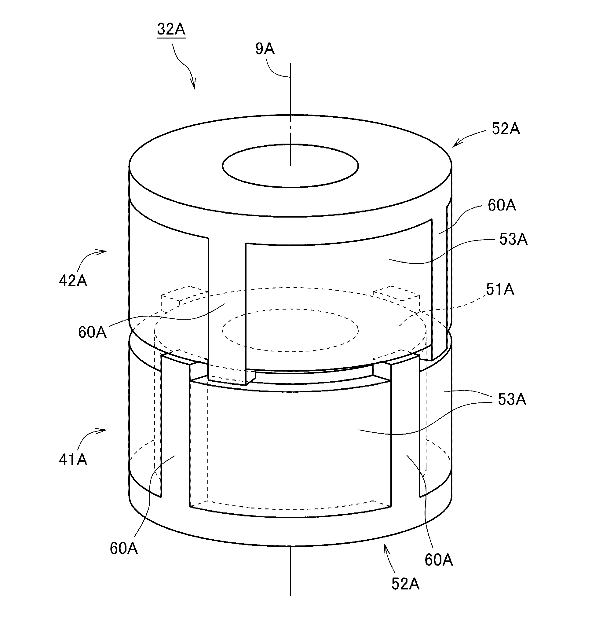
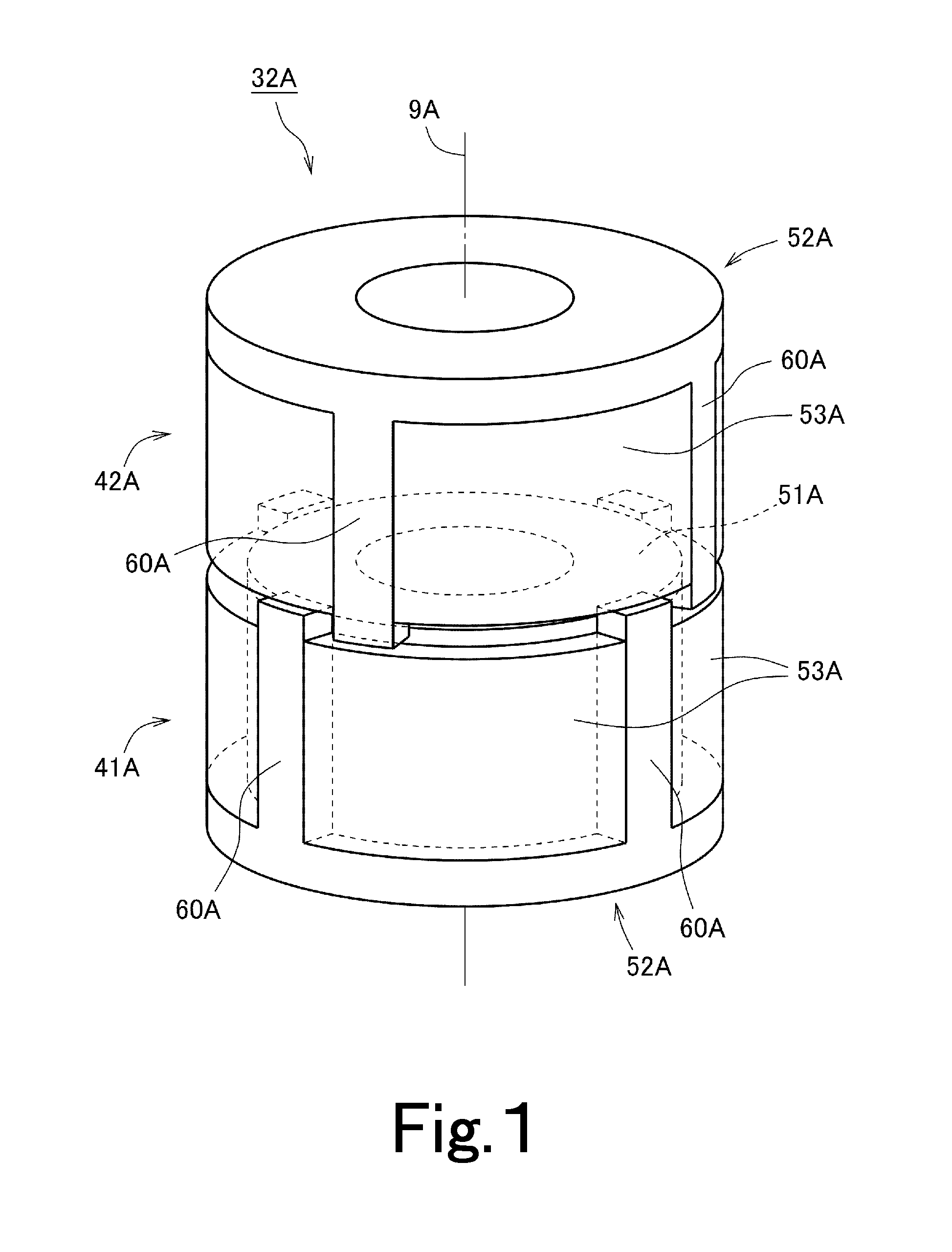
[0024]FIG. 1 is a perspective view of a rotor unit 32A for a rotating electrical machine according to a preferred embodiment of the present invention.
[0025]As shown in FIG. 1, the rotor unit 32A preferably includes two rotating bodies 41A and 42A. The two rotating bodies 41A and 42A a...
PUM
| Property | Measurement | Unit |
|---|---|---|
| Shape | aaaaa | aaaaa |
| Dimension | aaaaa | aaaaa |
Abstract
Description
Claims
Application Information