Carrier for installing and removing storage batteries from confined spaces

Inactive Publication Date: 2013-10-24
KERSELL JR ALBERT C
View PDF2 Cites 3 Cited by
  • Summary
  • Abstract
  • Description
  • Claims
  • Application Information

AI Technical Summary

Benefits of technology

This patent describes a battery carrier that allows for the safe installation and removal of batteries from cramped spaces. The carrier includes two rigid elongated members that are connected together by a coupler. Each elongated member has a thin clasping member attached to it for clamping the sides of batteries. The elongated members have holes therein, and the coupler includes a bolt that passes through the holes. This allows the carrier to securely hold batteries of varying widths. A simple strapping system is also attached to the elongated members for lifting batteries. The technical effect of this invention is to provide a practical and safe way to install and remove batteries from tight spaces.

Problems solved by technology

I have found it difficult to install and remove storage batteries from cramped confined spaces that contain storage batteries on motorcycles.
Furthermore the batteries are heavy so that they can be dropped and injure the person removing or installing the batteries and thus there is a need for the battery carrier to have a very strong grip on the sides of the batteries without straining the person using the battery carrier.
Rayburn U.S. Pat. No. 4,215,889 and Straus U.S. Pat. No. 4,527,823 utilize two handles which could strain the hand of the user resulting in a “hard squeeze” and would increase manufacturing costs.
They also lack a spaced series of linear holes for providing a carrier for storage batteries of various sizes.
They also do not disclose substantially flat battery gripping surfaces.

Method used


Image

  • Carrier for installing and removing storage batteries from confined spaces
  • Carrier for installing and removing storage batteries from confined spaces
  • Carrier for installing and removing storage batteries from confined spaces

Examples


Embodiment Construction

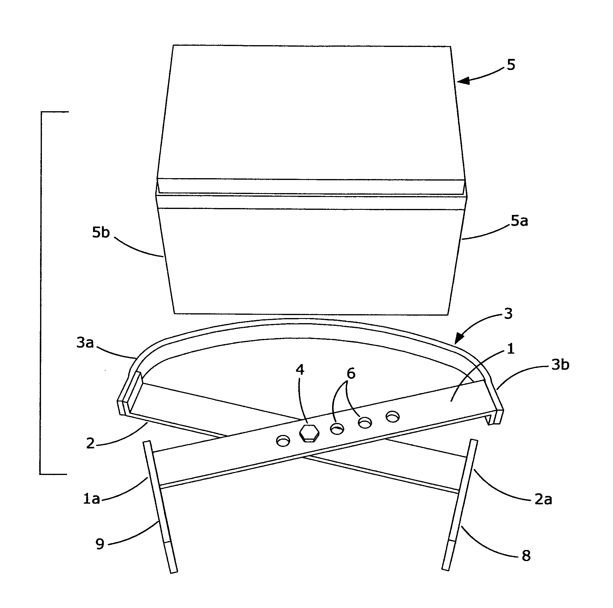
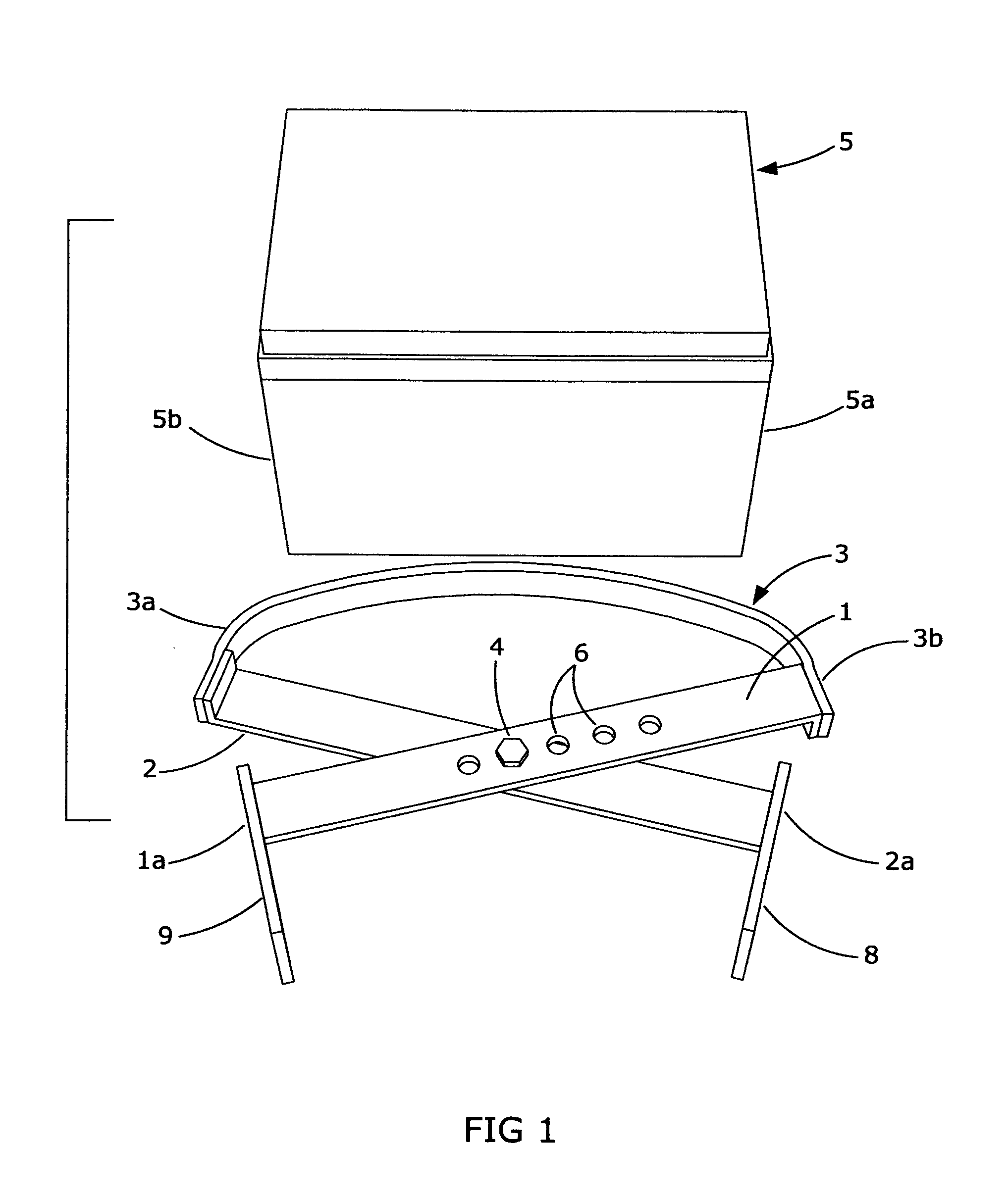
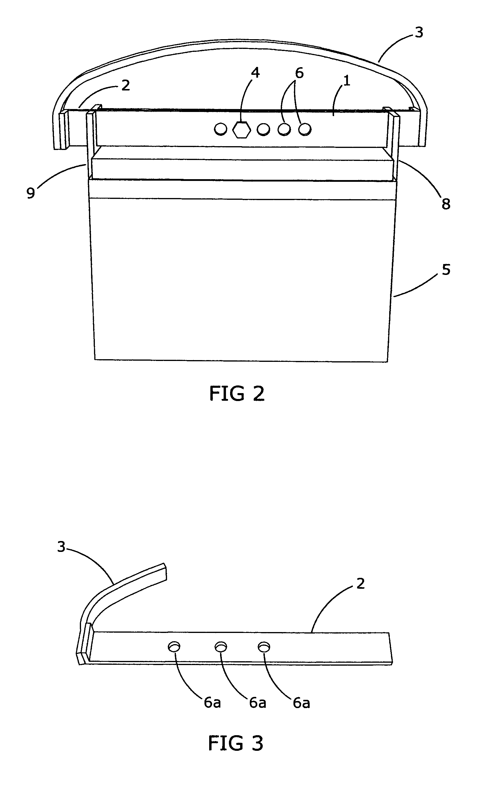
[0004]A storage battery carrier for safely installing and removing storage batteries from cramped confined spaces includes a coupler for rotatably coupling a pair of rigid elongated members together, each elongated member having a substantially flat thin clasping member affixed thereto for clasping the sides of storage batteries of varying widths. At least one of the elongated members have several holes therein and the coupler includes a bolt that passes through the holes in the first and second elongated members. The holes are positioned with respect to the very thin substantially flat clasping members so that by selectively passing the bolt through particular holes in the first elongated member, the clasping members will be positioned very close to the sides of a battery having a particular width, enabling the carrier to safely install and remove batteries from cramped spaces. A simple single strap affixed to the elongated members actuates battery lifting.

BRIEF DESCRIPTION OF THE ...


PUM


Abstract

A storage battery carrier for safely installing and removing storage batteries from cramped confined spaces includes a coupler for rotatably coupling a pair of elongated members together, each elongated member having a substantially flat thin roughened clasping member affixed thereto for clasping the sides of storage batteries of varying widths. Both elongated members have one or more holes therein and the coupler includes a bolt that passes through the holes in the first and second elongated members. The holes are positioned with respect to the very thin flat clasping members so that by selectively passing the bolt through particular holes in the first and second elongated members, the clasping members will be positioned very close to the sides of batteries having a particular width enabling the carrier to safely install and remove batteries from cramped spaces. A simple single strap affixed to the elongated members actuates battery lifting.

Description

BACKGROUND OF THE INVENTION[0001]I have found it difficult to install and remove storage batteries from cramped confined spaces that contain storage batteries on motorcycles. The sides of the storage batteries must be moved about, e.g. by rocking the batteries back and forth, in removing them from such confined spaces. Furthermore the batteries are heavy so that they can be dropped and injure the person removing or installing the batteries and thus there is a need for the battery carrier to have a very strong grip on the sides of the batteries without straining the person using the battery carrier.[0002]Viola U.S. Pat. No. 4,678,217 discloses a non-adjustable “scissor” storage battery carrier having teeth that can puncture plastic cased batteries and are not wafer thin for grasping storage batteries in tight compartments. Also no spaced series of linear aligned holes are disclosed for providing a substantial adjustment range for large and small batteries.[0003]Rayburn U.S. Pat. No. ...

Claims


Application Information

Patent Timeline
IPC IPC(8): B66C1/42
CPCB65G7/12
Inventor KERSELL, JR., ALBERT C.
Owner KERSELL JR ALBERT C
Why Eureka
Try Eureka