Electric vehicle

a technology of electric vehicles and electric motors, applied in the direction of electric propulsion mounting, bicycles, transportation and packaging, etc., can solve the problems of increasing the number of components, double the number of gear trains, and insufficient charging efficiency of regenerative energy

Inactive Publication Date: 2013-10-31
HONDA MOTOR CO LTD
View PDF18 Cites 23 Cited by
  • Summary
  • Abstract
  • Description
  • Claims
  • Application Information

AI Technical Summary

Benefits of technology

[0026]According to the eleventh and twelfth embodiments, the drive- and regeneration-side transmission ratios can be set compactly by use of the one-way clutches even in a case of mounting the speed reduction mechanism inside the swingarm.

Problems solved by technology

Thus, the efficiency of charging with regenerative energy is not sufficiently high.
However, doing so doubles the number of gear trains and therefore inevitably increases the number of components, thereby causing a problem of increase in the size of the speed reduction mechanism.

Method used


Image

  • Electric vehicle
  • Electric vehicle
  • Electric vehicle

Examples


Embodiment Construction

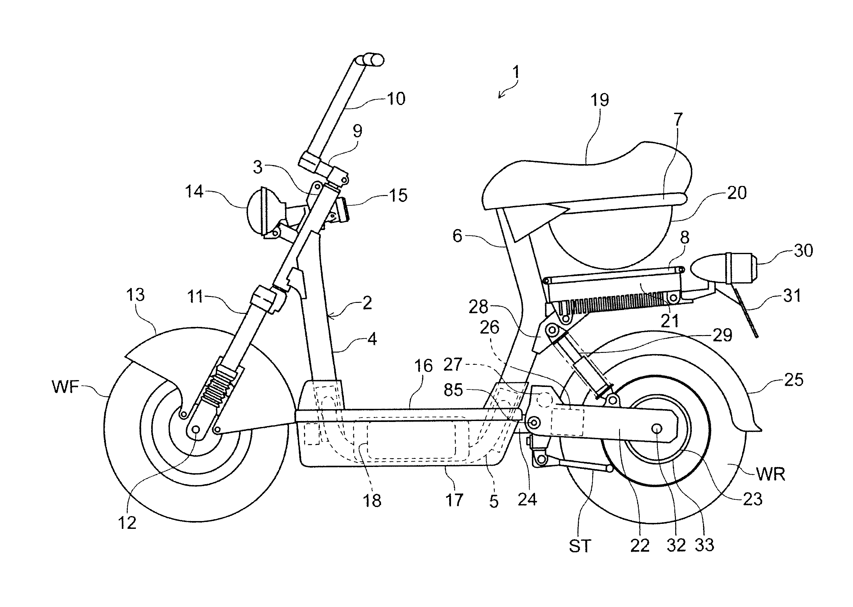
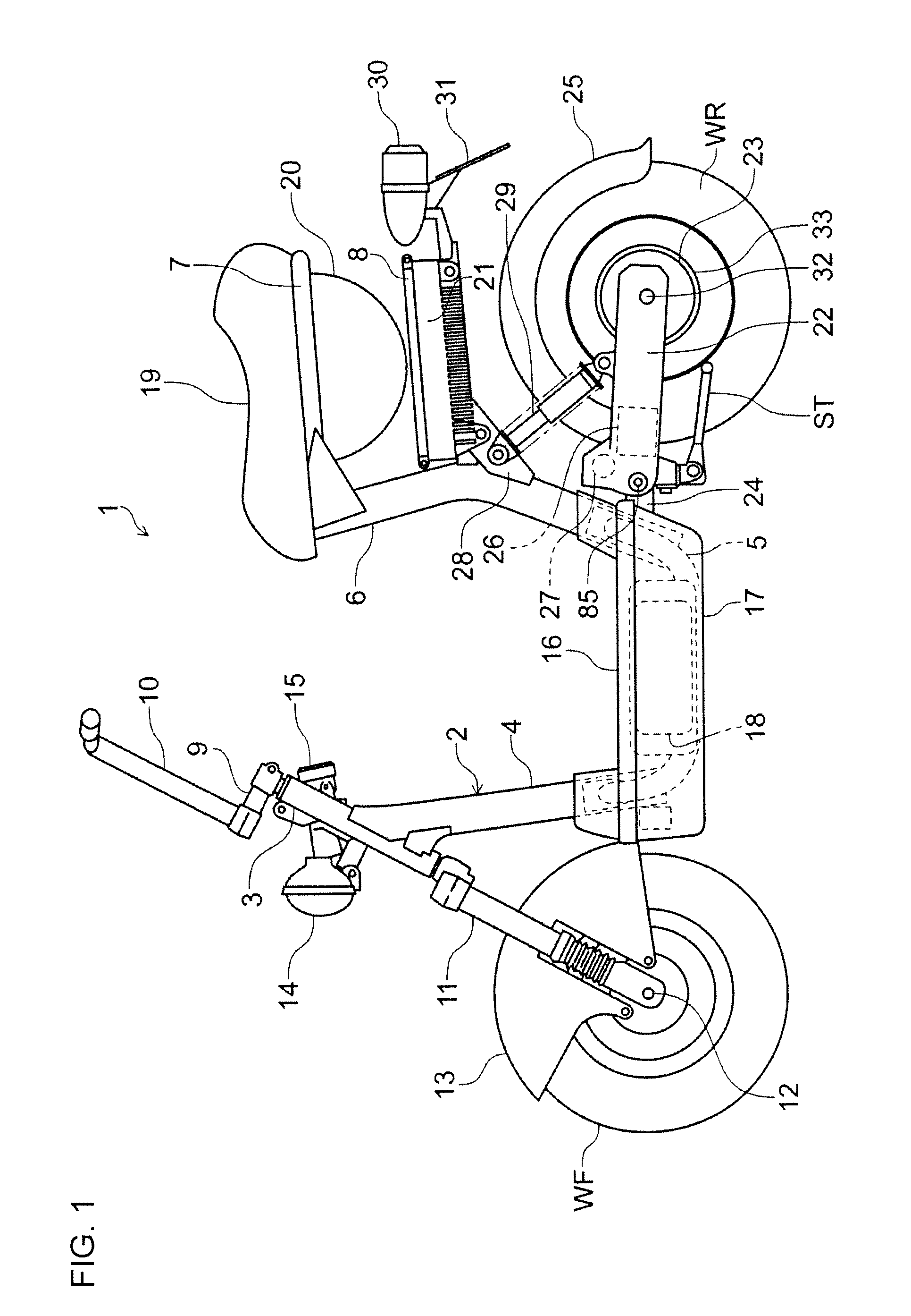
[0045]Hereinbelow, preferred embodiments of the present invention will be described in detail with reference to the drawings. FIG. 1 is a left-side view of an electric vehicle including a power unit according to an embodiment of the present invention. A main frame 2 of an electric vehicle 1 is formed of a head pipe 3, a down pipe 4 extending downward from the head pipe 3, a pair of left and right lower pipes 5 joined at the front end to the down pipe 4 and extending horizontally rearward, a seat post 6 connected to the rear end of each lower pipe 5 and extending upward, a seat frame 7 extending horizontally rearward from the upper end of the seat post 6, and a middle frame 8 situated below the seat frame 7 and extending horizontally rearward from the seat post 6.

[0046]A steering handlebar 10 is coupled through an arm 9 to the upper end of a steering shaft (not shown) vertically penetrating the inside of the head pipe 3. A pair of left and right front forks 11 is coupled to the lower...


PUM


Abstract

An electric vehicle can include a power unit including a speed reduction device coupled to a motor output shaft. Two systems can be provided which are a drive-power transmission path to transmit rotation of a motor to a wheel hub, and a regenerative-power transmission path to transmit rotation of the hub to the motor. A drive-side one-way clutch is provided between the hub and a second internal gear being the final-stage gear in the drive-power transmission path and is configured to transmit rotation of the drive-side final-stage gear to the hub. A regeneration-side one-way clutch is provided between the hub and a regeneration-side first-stage gear and is configured to transmit rotation of the hub to the regeneration-side first-stage gear.

Description

BACKGROUND[0001]1. Field[0002]The present invention relates to an electric vehicle and relates particularly to an electric vehicle including a reduction gear device for transmitting the output of an electric motor to a drive wheel, and also for regenerating electric energy by transmitting rotation of the drive wheel to the electric motor.[0003]2. Description of Related Art[0004]Various power transmission mechanisms for electric vehicles have been studied. For example, in an electric vehicle described in Patent Document 1 (Japanese Patent Application Publication No. 2004-352208), an electric motor held on a swingarm is disposed on a lateral side of a drive wheel, and power from the electric motor is transmitted to the drive wheel through a reduction gear device. The reduction gear device is housed within the width of the drive wheel and includes a tooth portion which is formed around the tip of an output shaft of the electric motor and a tooth portion around an axle which meshes with...

Claims


Application Information

Patent Timeline
Patent Type & Authority Applications(United States)
IPC IPC(8): B60L7/18
CPCB60L7/18B60L15/2054B60L2200/12B62K11/10B62K2202/00Y02T10/72Y02T10/64
Inventor MURAKAMI, HISASHIYOSHINO, TSUTOMUAOKI, KOJI
Owner HONDA MOTOR CO LTD
Why Eureka
Try Eureka