Touch sensing display panel and touch sensing liquid crystal display panel

Active Publication Date: 2013-11-28
AU OPTRONICS CORP
View PDF7 Cites 69 Cited by
  • Summary
  • Abstract
  • Description
  • Claims
  • Application Information

AI Technical Summary

Benefits of technology

[0011]In the touch sensing display panel of the present invention, since the auxiliary electrode is disposed on the inner surface of the first substrate in the sealant region, the spacing between the connection pads overlapping the se

Problems solved by technology

However, in the conventional in-cell type touch sensing display panels, the connecting lines, which electrically connect the touch sensing device to a device outside the touch sensing device, are not uniformly distributed on a periphery region of a color filter substrate; therefore, the thickness of films disposed on the inner surface in the periphery region of the color filter substrate varies a lot and is uneven.
Therefore, if the thickness of the films on the inner surface of the color filter substrate varie

Method used


Image

  • Touch sensing display panel and touch sensing liquid crystal display panel
  • Touch sensing display panel and touch sensing liquid crystal display panel
  • Touch sensing display panel and touch sensing liquid crystal display panel

Examples


Embodiment Construction

[0022]To provide a better understanding of the present disclosure, the embodiments will be described in detail. The embodiments of the present disclosure are illustrated in the accompanying drawings with numbered elements. In addition, the terms such as “first” and “second” described in the present disclosure are used to distinguish different components or processes, which do not limit the sequence of the components or processes.

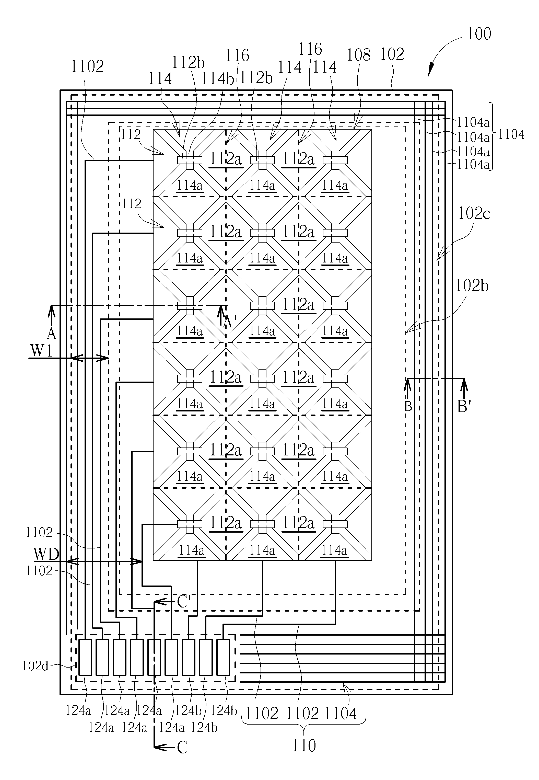
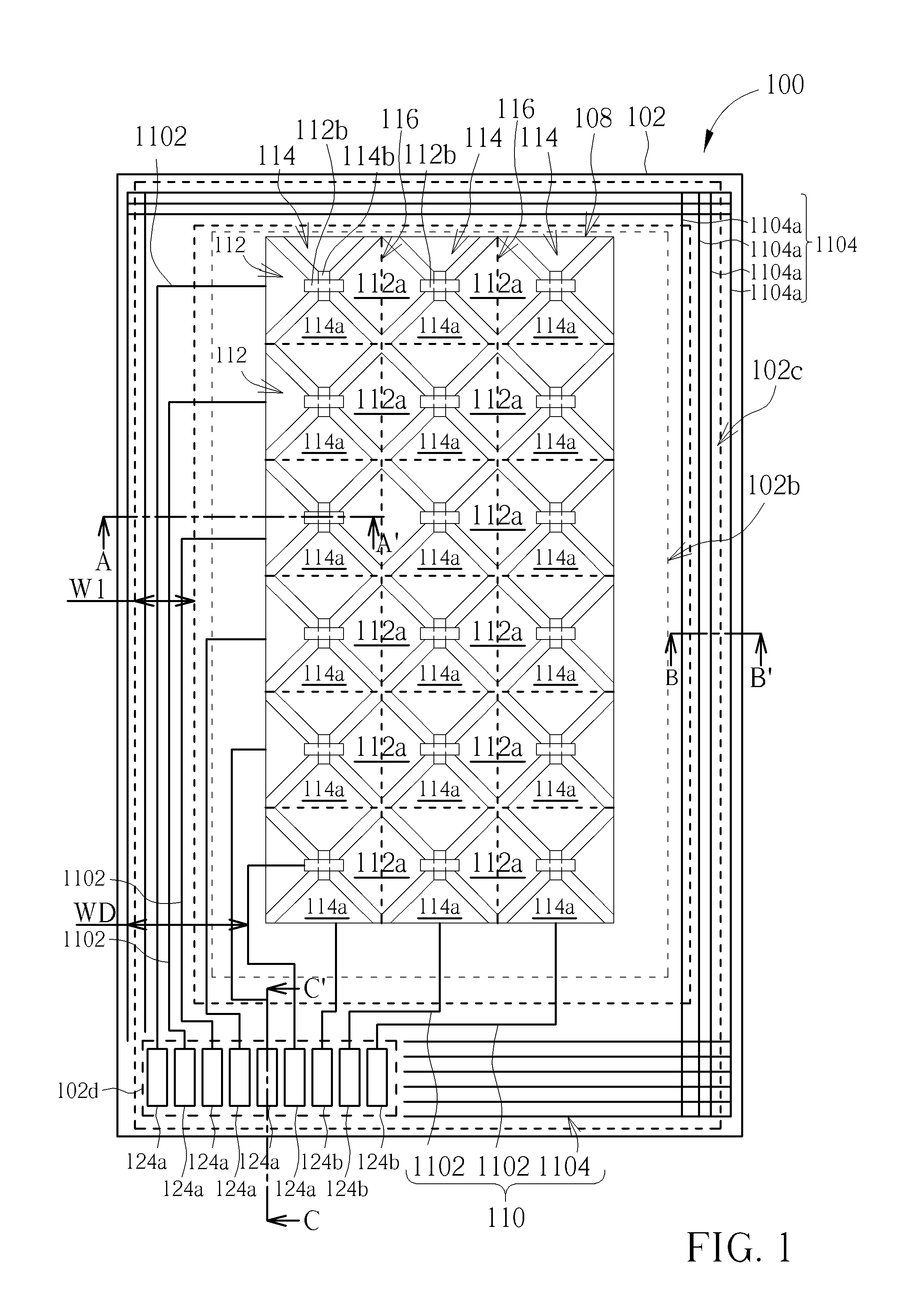
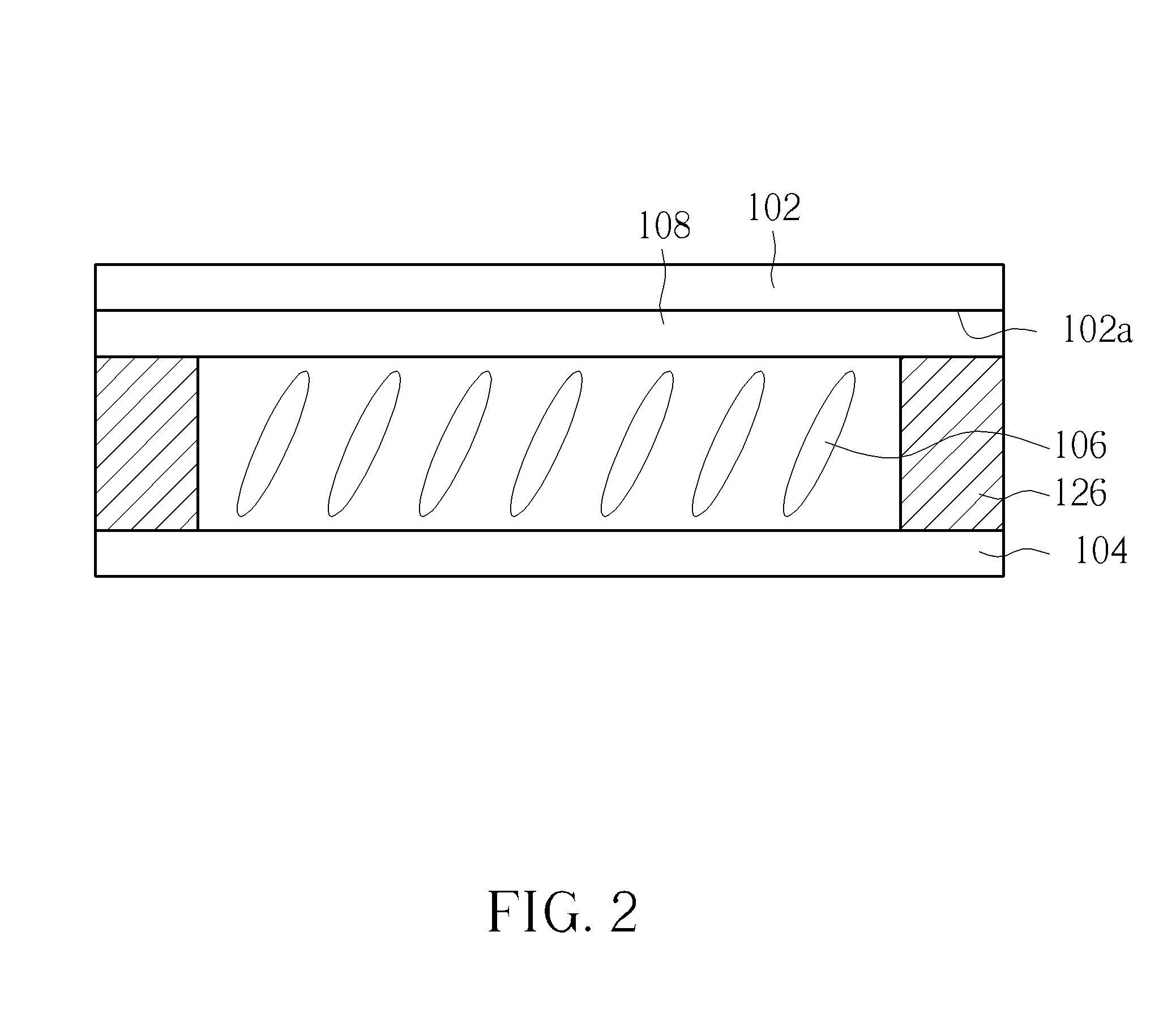
[0023]Please refer to FIGS. 1-2. FIG. 1 is a schematic diagram illustrating a top view of a touch sensing display panel according to a first embodiment of the present invention. FIG. 2 is a schematic diagram illustrating a cross-sectional view of the touch sensing display panel in a touch sensing region according to the first embodiment of the present invention. As shown in FIGS. 1-2, the touch sensing display panel 100 includes a first substrate 102, a second substrate 104, a display medium layer 106, a sealant 126, a touch sensing device 108, and a pattern...


PUM


Abstract

A touch sensing display panel includes a first substrate, a second substrate, a touch sensing device, a patterned electrode layer, an insulating layer, and a sealant. The first substrate has a touch sensing region, and a sealant region surrounding the touch sensing region. The touch sensing device is disposed on an inner surface of the first substrate in the touch sensing region. The patterned electrode layer is disposed on the inner surface of the substrate in the sealant region, and the patterned electrode layer includes a plurality of connecting lines electrically connected to a touch sensing device, and an auxiliary electrode. The auxiliary electrode is not directly electrically connected to the connecting lines and the touch sensing device. The sealant is disposed between the first substrate and the second substrate in the sealant region, and at least one of the connecting lines and the auxiliary electrode overlap the sealant.

Description

BACKGROUND OF THE INVENTION[0001]1. Field of the Invention[0002]The present invention relates to a touch sensing display device and a touch sensing liquid crystal display device, and more particularly, to a touch sensing display device and a touch sensing liquid crystal display device with uniform display quality.[0003]2. Description of the Prior Art[0004]Because of the intelligent characteristics of human-computer interaction, touch sensing display panels have been widely applied to the external input interfaces of many instruments. In recent years, as the applications of electronic products have developed diversely, consumer electronics with the integration of touch sensing functions and display panels are commercialized a lot and have evolved flourishingly, for example, mobile phones, GPS navigator systems, tablet PCs, personal digital assistances (PDA), and laptop PCs.[0005]Generally, a touch sensing display panel includes a display panel and a touch sensing panel. The touch sen...

Claims


Application Information

Patent Timeline
IPC IPC(8): G06F3/044G02F1/1333
CPCG06F3/044G02F1/13338G06F3/0412G06F3/04164G06F3/0443G06F3/0446G06F2203/04112
Inventor TSAI, HSIN-LICHIEN, YU-FENGYANG, TUN-CHUN
Owner AU OPTRONICS CORP
Why Eureka
Try Eureka