Method and apparatus for sealing a glass package

a technology of glass package and glass shell, which is applied in the field of glass package sealing methods and apparatuses, can solve the problems of insufficient weight of the substrate in and of itself to facilitate a good seal, great effort is made to provide a hermetic package, and the leakage rate is unacceptable for a long device life. to achieve the effect of improving the seal quality of the glass packag

Inactive Publication Date: 2011-03-31
CORNING INC
View PDF9 Cites 3 Cited by
  • Summary
  • Abstract
  • Description
  • Claims
  • Application Information

AI Technical Summary

Benefits of technology

[0010]An apparatus and method are disclosed that can improve the seal quality of a glass package, and in particular a glass package comprising one or more organic light emitting diode devices. In one broad aspect the present invention is used to apply a force against an assembly comprising first and second glass substrates, and including a sealing material disposed therebetween. Simultaneous with the application of the force, a beam of electromagnetic energy is used to irradiate the sealing material, thereby connecting the first substrate to the second substrate according to the nature of the sealing material. For example, if the sealing material is an adhesive, such as an epoxy adhesive, the incident energy beam may cure the adhesive. If the sealing material is a glass-based frit, the energy beam can be used to heat and soften the frit to form the seal. Both the energy beam and the applied force are traversed over the length of the sealing material to form a sealed glass package. Preferably, the glass package is hermetically sealed such that oxygen and / or water do not penetrate the seal at more than about 10−3 cc / m2 / day and / or 10−6 g / m2 / day, respectively. Thus, the life of an organic light emitting diode (OLED) device that may be disposed between the first and second substrates and encircled by the sealing material may advantageously be extended.
[0011]The force is applied by a fluid bearing element that applies a force against the glass assembly without contacting the assembly. Preferably, the force is applied against the assembly in proximity to the point on the assembly at which the energy beam impinges. That is, it is preferably that the fluid bearing element or elements generally encircle the point at which the beam impinges the assembly so that the force is relatively uniformly applied to the substrate(s) and transmitted to the sealing material. Thus, contact between the sealing material and the substrates can be improved by causing the sealing material to spread against the substrates. Moreover, the force applied by the method and apparatus disclosed herein can mitigate against unevenness in the height of the sealing material above the substrate on which the sealing material may be dispensed. This unevenness can result in a poor seal between the substrates.

Problems solved by technology

Therefore, great effort is made to provide a hermetic package to contain the OLED devices.
However, adhesives, such as various epoxies, tend to have unacceptable leakage rates for long device life, thereby requiring a desiccant to be disposed within the sealed glass package to absorb moisture and / or various gases which may penetrate the seal, or which may be generated during curing of the adhesive seal.
However, the weight of the substrate in and of itself is insufficient for facilitating a good seal.
Simply placing the aligned sheets of glass beneath the laser and sealing with the laser will produce a seal, but one that may have narrow patches as well as delamination defects, which are both caused by irregularities in the dispensed sealing material (e.g. frit).
These artifacts of the sealing process may have a severely detrimental effect on the life and performance of an OLED device disposed between the substrates.
This unevenness can result in a poor seal between the substrates.

Method used


Image

  • Method and apparatus for sealing a glass package
  • Method and apparatus for sealing a glass package
  • Method and apparatus for sealing a glass package

Examples


examples

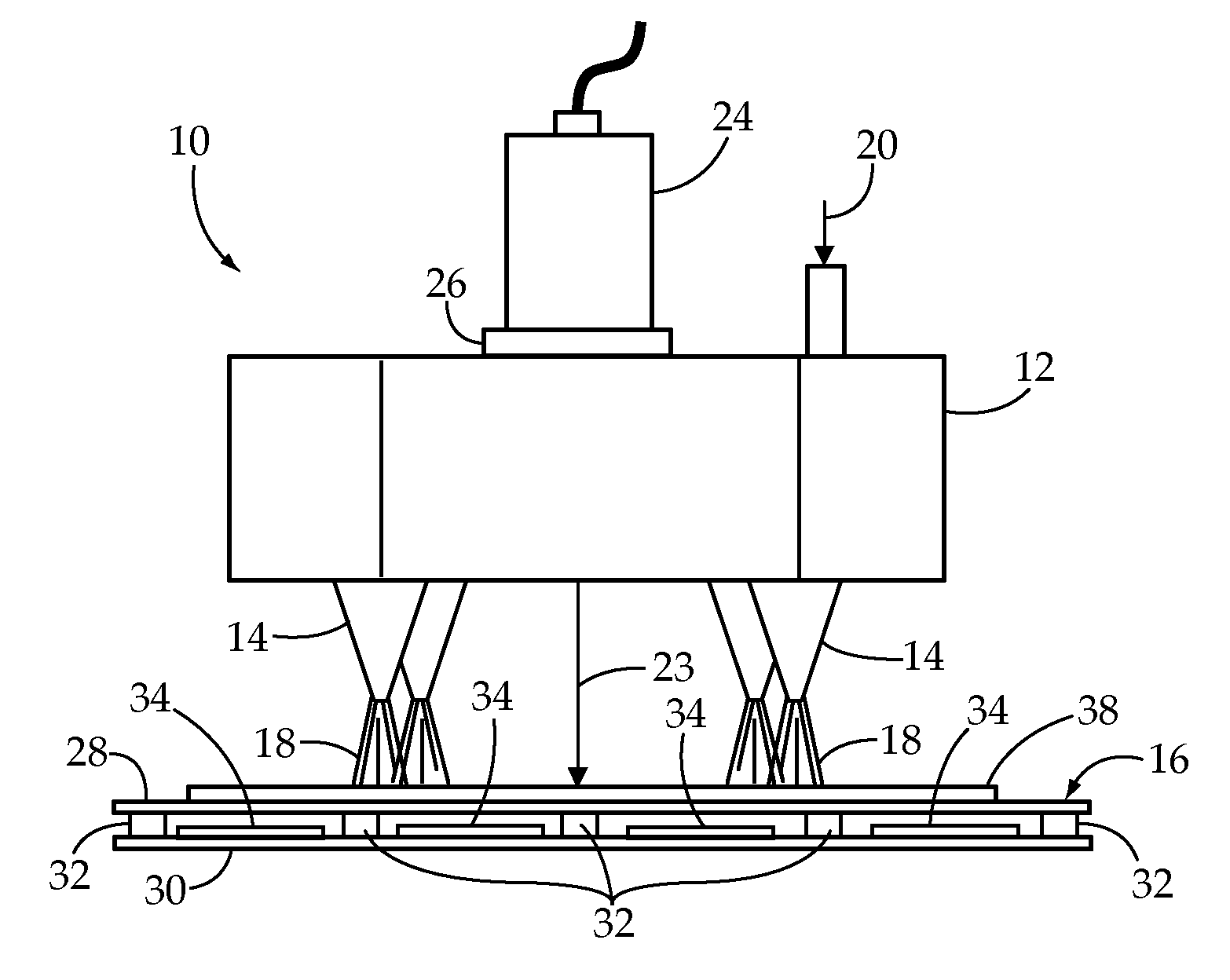
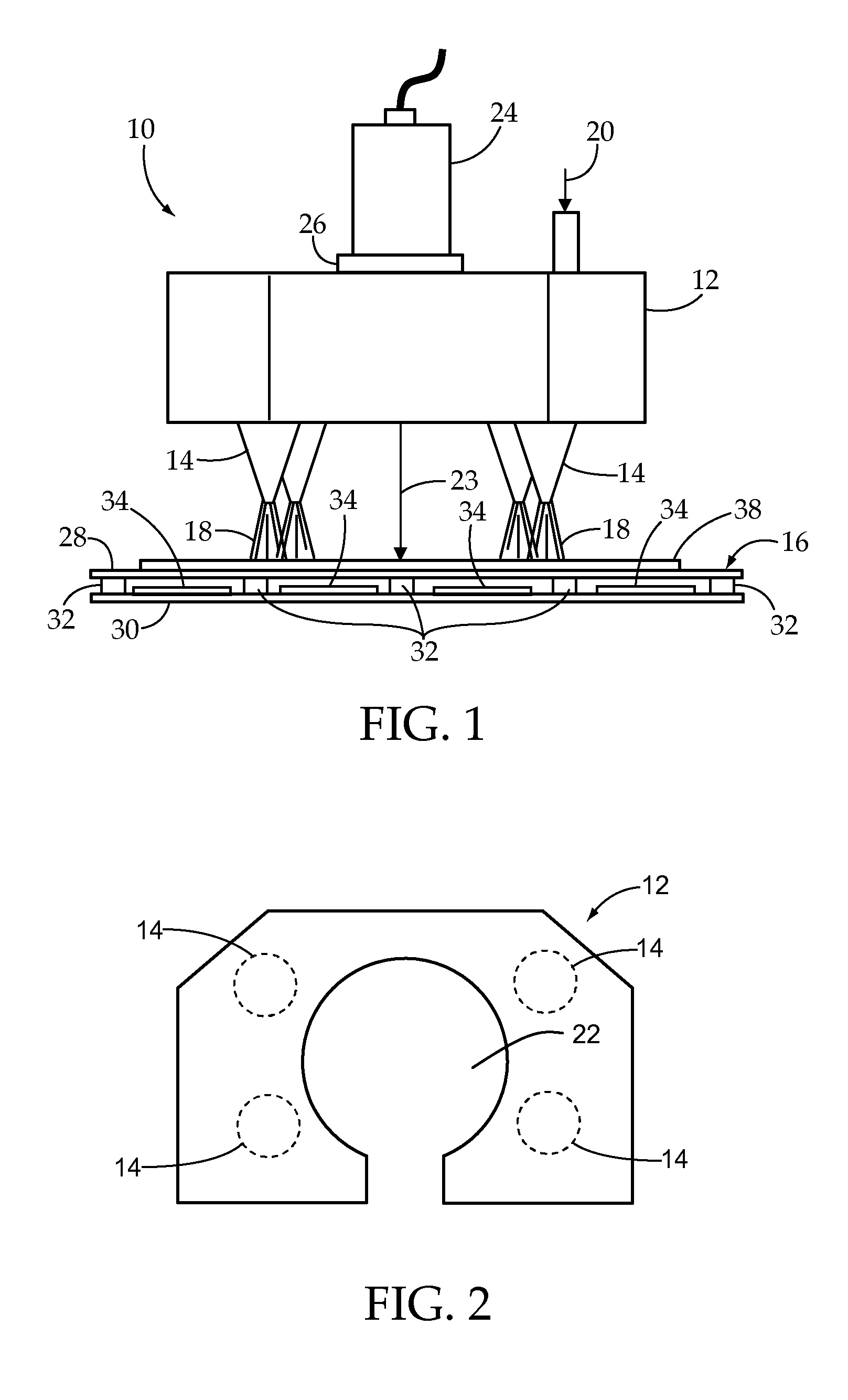
[0048]In one experiment, four Exair model # 1009 air nozzles were disposed in a radially symmetric pattern around a laser that was itself disposed in an aluminum housing and mounted such that the direction of airflow was perpendicular to the upper glass substrate surface of a glass assembly as previously described. The housing included four press-fit air hose connectors for ½″ OD hose with which to supply the nozzles with compressed air. The hose was connected to a compressed air feed with a regulator to adjust the pressure and fine tune it to the desired amount. The air jet assembly (housing and nozzles) was slipped over the laser collet and screwed into place. The sealing height (from the surface of the glass to the bottom edge of the laser) was approximately 26 mm, with the tips of the nozzles positioned about 10 mm below the laser (about 16 mm from the glass).

[0049]The air nozzles were adjustable to different flow outputs, and thus different forces. In this experiment they were ...


PUM

PropertyMeasurementUnit
temperaturesaaaaaaaaaa
thicknessaaaaaaaaaa
thicknessaaaaaaaaaa

Abstract

An apparatus for sealing a substrate assembly by applying a force to the assembly while simultaneously exposing the substrate assembly, and in particular a sealing material disposed between two substrates of the substrate assembly, to an irradiating beam of electromagnetic energy. The beam heats, cures and / or melts the sealing material, depending upon the sealing material to form the seal. The force is applied by directing a flow of fluid against the substrate assembly, and beneficially improves contact between the substrates of the substrate assembly and the sealing material during the sealing process, therefore assisting in achieving a hermetic seal between the substrates.

Description

[0001]This application claims the benefit of U.S. Provisional Application No. 60 / 997,817 filed Oct. 5, 2007, entitled “METHOD AND APPARATUS FOR SEALING A GLASS PACKAGE”.BACKGROUNDField of the Invention[0002]This invention relates to a method and an apparatus for forming a glass package, and in particular for sealing a glass assembly comprising an organic light emitting diode display device by irradiating the glass assembly with electromagnetic energy.TECHNICAL BACKGROUND[0003]Flat panel display devices, such as liquid crystal and plasma display devices for use in televisions, continue to replace cathode ray tube display devices as the display of choice for a broad array of applications, from cell phones to televisions.[0004]More recently, organic light emitting diode (OLED) display devices have made progress in the market place. Unlike LCD displays, which utilize a liquid crystal layer to alternately pass and block a light source, and plasma displays which emit light from a charged ...

Claims


Application Information

Patent Timeline
Patent Type & Authority Applications(United States)
IPC IPC(8): B29C65/14
CPCC03C23/001C03C23/002C03C23/0025C03C27/06C09J5/00Y10T156/1066C09J2400/143H05B33/04H05B33/10H01L51/5246Y10T156/1374C09J2205/31C09J2301/416H10K50/8426H10K71/00
Inventor AMSDEN, JEFFREY MICHAELBERNAS, JAMES JOSEPHCOSTELLO, III, JOHN JOSEPHGENTILE, MARGARET HELENSTOCKER, MARK ANDREWZHANG, LU
Owner CORNING INC
Why Eureka
Try Eureka