Closure with application guide

a technology of application guide and closure, which is applied in the field of container closure and package, can solve the problems of closure cocking, application equipment itself can create application defects, and the closure is not applied properly, and achieves the effect of reducing the angl

Active Publication Date: 2013-12-05
CLOSURE SYST INT INC
View PDF4 Cites 5 Cited by
  • Summary
  • Abstract
  • Description
  • Claims
  • Application Information

AI Technical Summary

Benefits of technology

[0013]The thickness of the one or more application guide elements will have a relationship to the amount of angle covered by the one or more guide elements. Increasing the thickness of the guide element will ordinarily decrease the amount of angle that it can cover or engage the container, without inhibiting the ability to engage or “hook” the container thread formation.
[0014]It is contemplated that closure diameter will have an effect on the potential size of the application guide element, with regard to both the thickness of the guide element, and its circumferential extent. The degree to which the closure can tilt will be affected by the height of the closure, the diameter of the closure, and the relationship between these two dimensions.

Problems solved by technology

Misapplication of closures can occur when a closure becomes “cocked” or otherwised misaligned with the container as the closure is rotatably applied and threaded onto the external threads of the container neck.
Experience has shown that features of the tamper-evident portion of the closure can sometimes result in misapplication, such as can occur if a projection or like tamper-evident feature on the closure pilfer band engages the container threads, acting to pull the closure partially out of the application chuck, resulting in cocking of the closure.
In some instances, the application equipment itself can create application defects, such as can occur if a bottle is slightly offset from the associated closure, or is slightly angled with respect to the closure.

Method used


Image

  • Closure with application guide
  • Closure with application guide
  • Closure with application guide

Examples


Embodiment Construction

[0022]While the present invention is susceptible of embodiment in various forms, there is shown in the drawings and will hereinafter be described presently preferred embodiments, with the understanding that the present disclosure is to be considered as an exemplification of the invention, and is not intended to limit the invention to the specific embodiments illustrated.

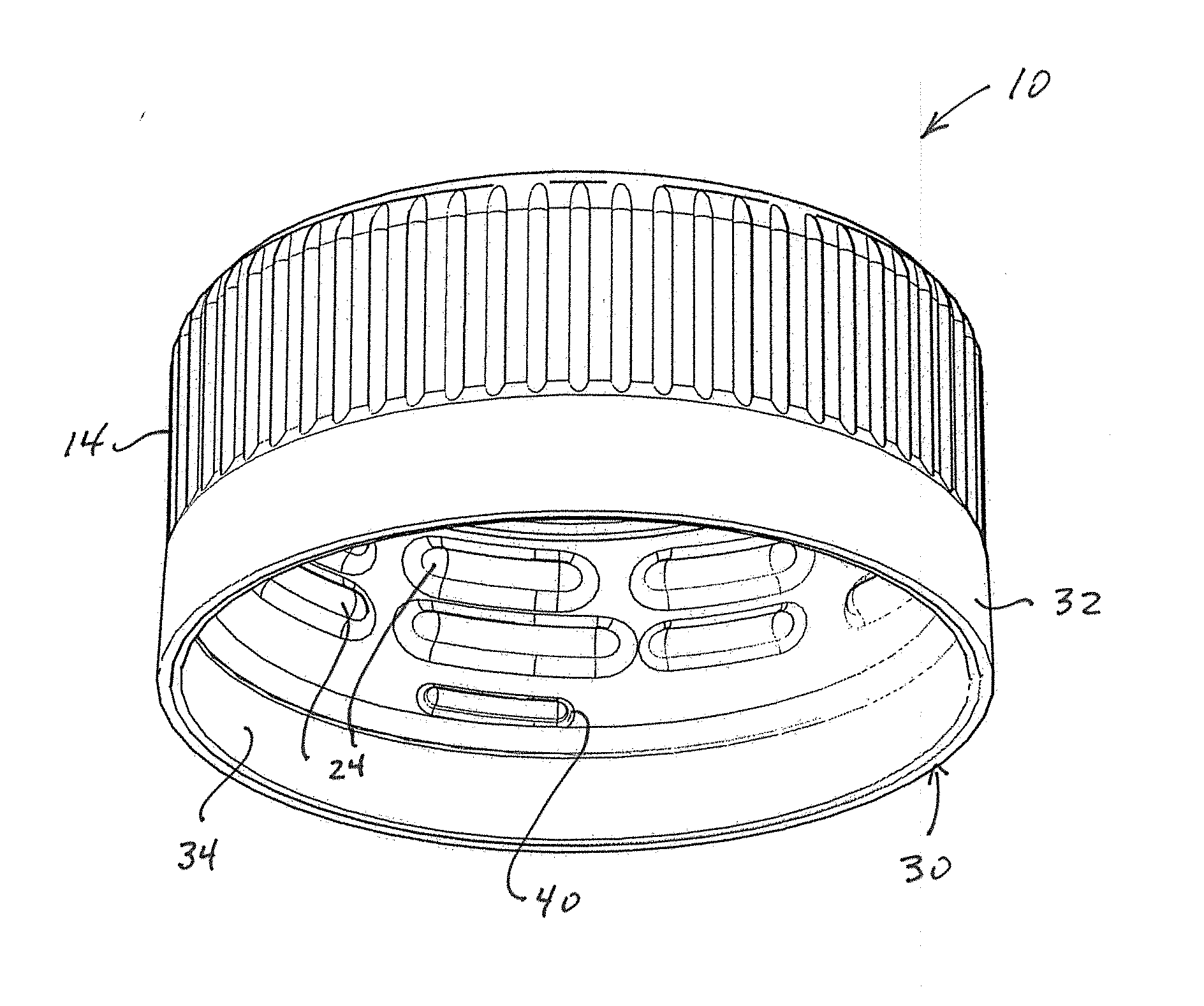
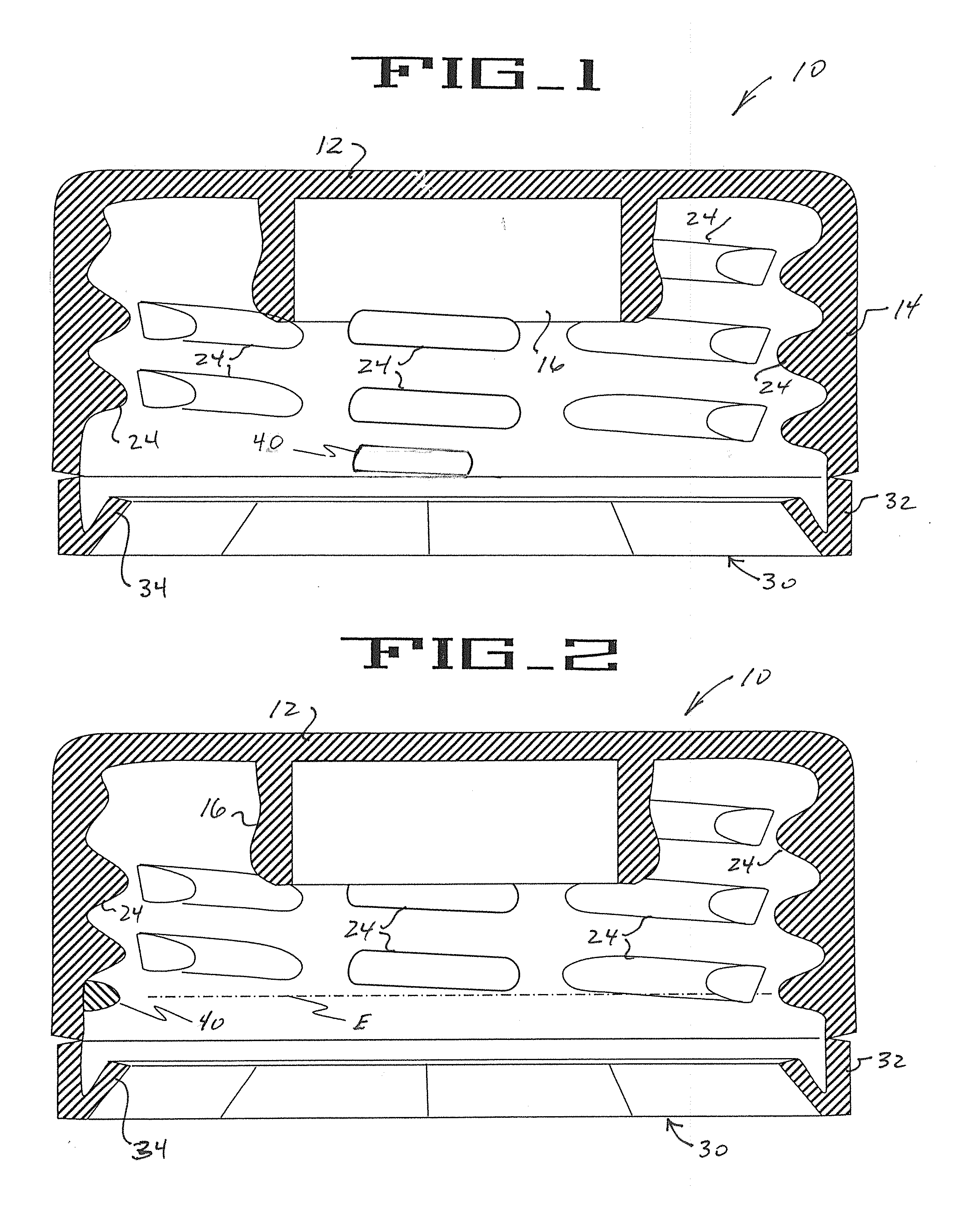
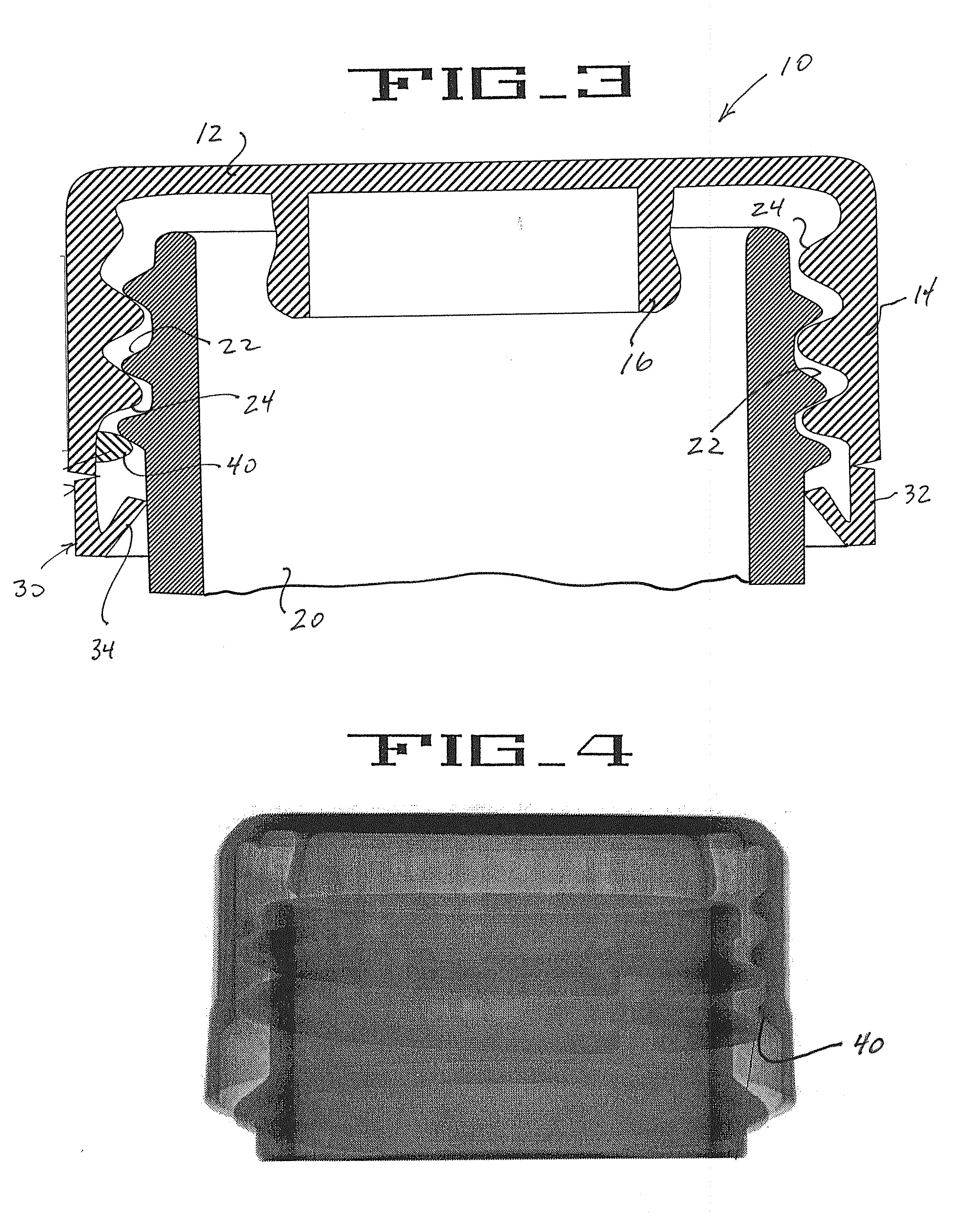
[0023]With reference to the drawings, FIGS. 1 and 2 illustrate a plastic closure 10 embodying the principles of the present invention. Plastic closure 10 can be efficiently molded from polymeric materials, such as polypropylene, polyethylene, copolymers, and the like, as are known in the art. Efficient formation can be effected by injection molding or compression molding.

[0024]In the illustrated embodiment, closure 10 includes a top wall portion 12, and an annular skirt portion 14 depending from the top wall portion 12. In the illustrated embodiment, the closure 10 is a so-called “linerless” closure, in that the clos...


PUM


Abstract

A plastic closure includes a top wall portion, and an annular depending skirt portion having at least one internal thread formation. In order to facilitate high-speed closure application to an associated container, the closure includes an application guide feature positioned in circumferentially spaced relationship to a thread start of the internal thread formation of the closure. The application guide feature is configured to engage the lower surface of an external thread formation of the associated container, whereby cocking, tilting, and other misalignment of the closure is avoided as it is applied to the container with high-speed application equipment.

Description

TECHNICAL FIELD[0001]The present invention relates generally to threaded plastic closures for use on bottles and like containers, and more particularly to a container closure, and package, wherein the closure includes an application guide feature to facilitate proper application of closures to containers with high-speed capping equipment.BACKGROUND OF THE INVENTION[0002]Threaded plastic closures have found widespread acceptance in the marketplace for use on bottles and like containers, including use for packaging of carbonated and non-carbonated beverages. Closures of this nature are formed from suitable polymeric materials by compression or injection molding, and can be configured to provide a tamper-evident or tamper-indicating function attendant to partial or complete removal from an associated container. A tamper-evident package includes a tamper-evident closure configured for cooperation with the associated container to provide the desired tamper-evidence.[0003]Cost-effective u...

Claims


Application Information

Patent Timeline
Patent Type & Authority Applications(United States)
IPC IPC(8): B65D41/38
CPCB65D41/38B65D2251/04B65D41/3428B65D41/34B65D41/04
Inventor EDIE, JOHNELLIOTT, DANIELGREEN, ERIN
Owner CLOSURE SYST INT INC
Why Eureka
Try Eureka