
Wireless energy transfer for implantable devices

a technology of implantable devices and wireless energy transfer, which is applied in the field of wireless energy transfer, can solve the problems of increasing the possibility of infection, reducing patient comfort, and limited wireless energy transfer systems of the past, and achieves the effect of improving the range and tolerable offset of source and device resonators

Active Publication Date: 2013-12-05
WITRICITY CORP
View PDF10 Cites 215 Cited by
  • Summary
  • Abstract
  • Description
  • Claims
  • Application Information

AI Technical Summary

Benefits of technology

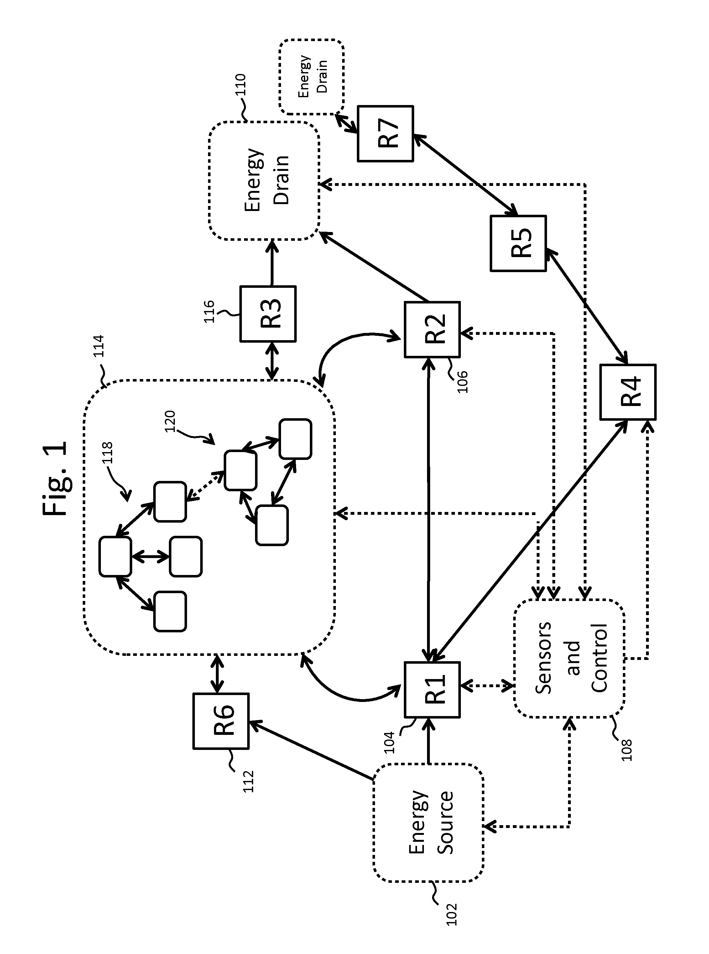
[0022]In embodiments the wireless energy transfer described herein improves the range and tolerable offset of source and device resonators with the use of repeater resonators that may be internal or external to a patient.
[0023]In embodiments, the source and device resonators may control the distribution of heat and energy dissipation by tuning elements of the source and the device.

Problems solved by technology

Prior art wireless energy transfer systems have been limited by a variety of factors including concerns over user safety, low energy transfer efficiencies and restrictive physical proximity / alignment tolerances for the energy supply and sink components.
In some patients and situations the implanted device requires constant or near constant operation and has considerable power demands that require connection to an external power source requiring percutaneous cables or cables that go through the skin of the patient to an external power source increasing the possibility of infection and decreasing patient comfort.

Method used


Image

  • Wireless energy transfer for implantable devices
  • Wireless energy transfer for implantable devices
  • Wireless energy transfer for implantable devices

Examples


Embodiment Construction

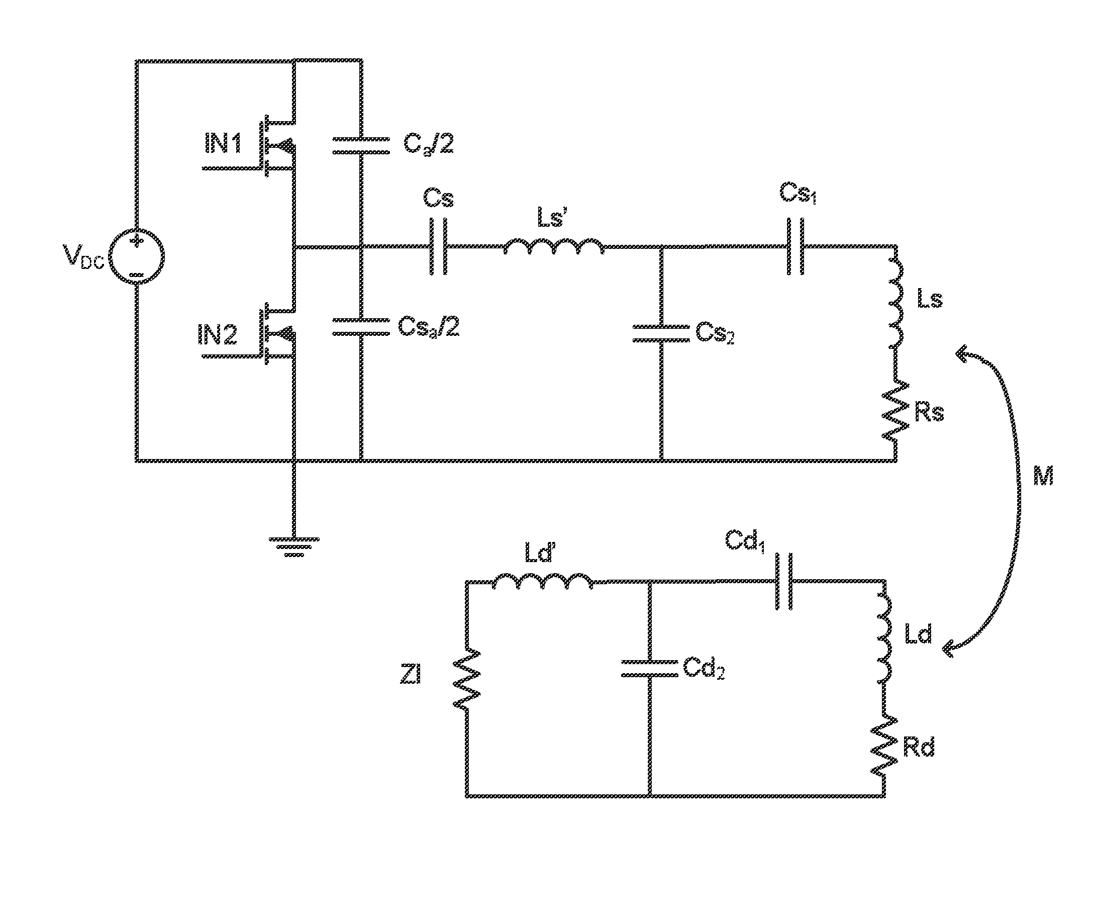
[0055]As described above, this disclosure relates to wireless energy transfer using coupled electromagnetic resonators. However, such energy transfer is not restricted to electromagnetic resonators, and the wireless energy transfer systems described herein are more general and may be implemented using a wide variety of resonators and resonant objects.

[0056]As those skilled in the art will recognize, important considerations for resonator-based power transfer include resonator efficiency and resonator coupling. Extensive discussion of such issues, e.g., coupled mode theory (CMT), coupling coefficients and factors, quality factors (also referred to as Q-factors), and impedance matching is provided, for example, in U.S. patent application Ser. No. 12 / 789,611 published on Sep. 23, 2010 as US 20100237709 and entitled “RESONATOR ARRAYS FOR WIRELESS ENERGY TRANSFER,” and U.S. patent application Ser. No. 12 / 722,050 published on Jul. 22, 2010 as US 20100181843 and entitled “WIRELESS ENERGY T...


PUM

PropertyMeasurementUnit
temperatureaaaaaaaaaa
resonant frequenciesaaaaaaaaaa

Abstract

Described herein are improved configurations for a wireless power transfer. Described are methods and designs for implantable electronics and devices. Wireless energy transfer is utilized to eliminate cords and power cables puncturing the skin to power an implantable device. Repeater resonators are employed to improve the power transfer characteristics between the source and the device resonators.

Description

CROSS-REFERENCE TO RELATED APPLICATIONS[0001]This application claims the benefit of U.S. Provisional Appl. No. 61 / 351,492 filed Jun. 4, 2010.[0002]This application is a continuation-in-part of U.S. Ser. No. 13 / 090,369 filed Apr. 20, 2011 which claims the benefit of U.S. Provisional Appl. No. 61 / 326,051 filed Apr. 20, 2010.[0003]The Ser. No. 13 / 090,369 application is a continuation-in-part of U.S. patent application Ser. No. 13 / 021,965 filed Feb. 7, 2011 which is a continuation-in-part of U.S. patent application Ser. No. 12 / 986,018 filed Jan. 6, 2011, which claims the benefit of U.S. Provisional Appl. No. 61 / 292,768 filed Jan. 6, 2010.[0004]This application is a continuation-in-part of U.S. patent application Ser. No. 12 / 986,018 filed Jan. 6, 2011 which claims the benefit of U.S. Provisional Appl. No. U.S. 61 / 292,768 filed Jan. 6, 2010.[0005]The Ser. No. 12 / 986,018 application is a continuation-in-part of U.S. patent application Ser. No. 12 / 789,611 filed May 28, 2010.[0006]The Ser. N...

Claims


Application Information

Patent Timeline
Patent Type & Authority Applications(United States)
IPC IPC(8): H01F38/14A61M60/178A61M60/191A61M60/289A61M60/875
CPCH01F2003/005H02J5/005H02J7/025H02J17/00H03H7/40B60L2200/26H04B5/0093H01F38/14Y02T10/7094Y02T10/7055H04B5/0037H02J50/12H02J7/0042H02J50/50H02J50/90H02J50/005A61M60/289A61M60/178A61M60/875A61M60/191H02J2310/23H02J50/70A61M2205/8243A61N1/3975
Inventor SCHATZ, DAVID A.KESLER, MORRIS P.HALL, KATHERINE L.GANEM, STEVEN J.
Owner WITRICITY CORP
Learn More