Air conditioning system

a technology of air conditioning system and airflow, which is applied in the direction of vehicle components vehicle heating/cooling devices, etc., can solve the problems of affecting affecting the acoustics and the quantity of air, and affecting the flow of cold air and warm air. to achieve the effect of improving the overall efficiency of the air conditioning system

Active Publication Date: 2014-01-09
MAHLE INT GMBH
View PDF46 Cites 10 Cited by
  • Summary
  • Abstract
  • Description
  • Claims
  • Application Information

AI Technical Summary

Benefits of technology

[0008]It is, therefore, the object of the present invention to provide an air conditioning system which permits the cold airflow and the warm airflow to be mixed in an advantageous manner, in order to produce the temperature stratification required to fulfill passenger requirements, without significantly reducing the flow cross sections or subjecting the airflows to large deflections. Moreover, the design of the air conditioning system is intended to be simple and cost-effective to produce.

Problems solved by technology

It is a particular drawback in the prior art that, by means of the flow guidance elements, cross sections in the cold air paths and warm air paths are occasionally partially blocked, and / or the cold airflows and warm airflows are subjected to considerable deflections.
Both influences also have a negative effect on the acoustics and the quantity of air.

Method used


Image

  • Air conditioning system
  • Air conditioning system
  • Air conditioning system

Examples


Embodiment Construction

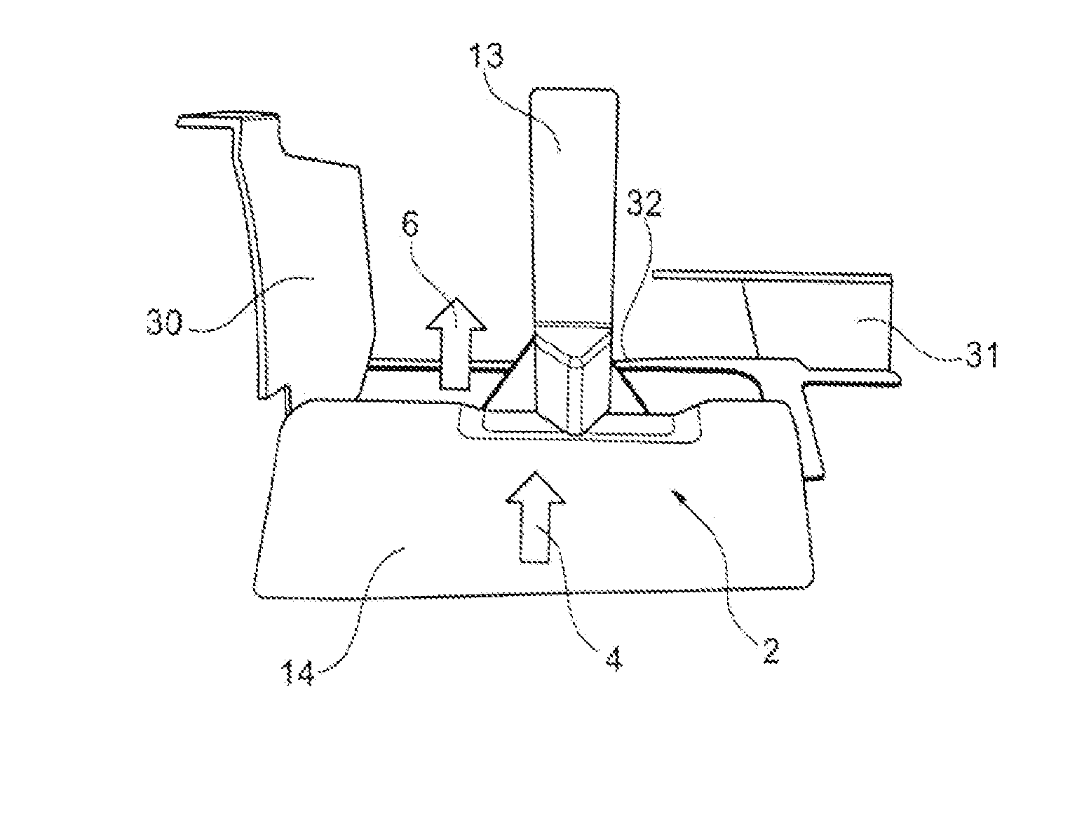
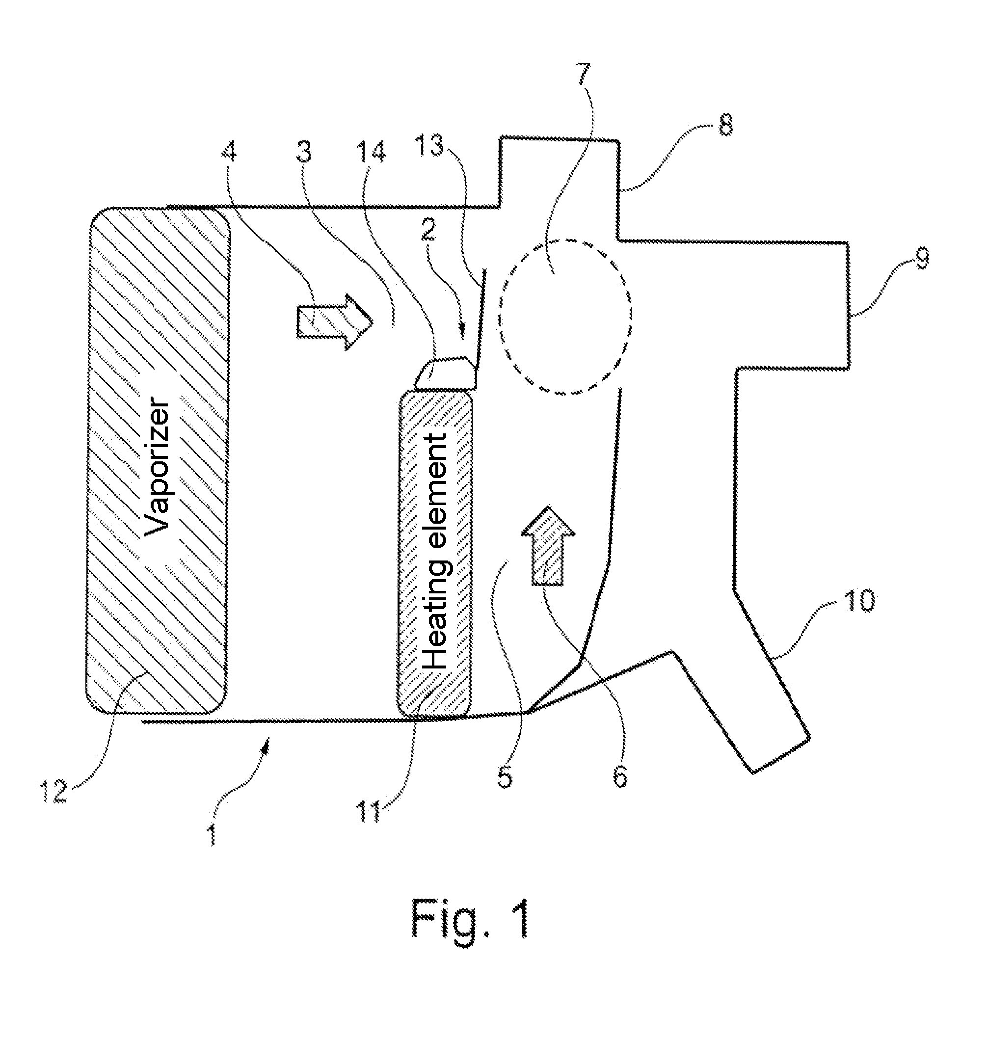
[0049]FIG. 1 shows a section through an air conditioning system 1. In this case, the air conditioning system 1 is shown in section. The air conditioning system 1 is shown in the illustration shown in FIG. 1, in particular in the region thereof which is arranged downstream of the vaporizer 12.

[0050]In current air conditioning systems 1 which are used for applications in motor vehicles, the airflow is subdivided after flowing through the vaporizer 12 into a region for cold air as well as a region for warm air. In the example shown in FIG. 1, a portion of the air which flows through the vaporizer 12 subsequently flows through the heating element 11. The quantity of air which has flowed through the heating element 11 then flows in the flow channel 5 as warm air 6 through the air conditioning system 1. The portion of air which does not flow through the heating element 11 after flowing through the vaporizer 12 flows in the flow channel 3 as cold air 4. In alternative embodiments, the reve...


PUM


Abstract

The invention relates to an air conditioning system, in particular for use in a motor vehicle, having a first flow channel for a first airflow which may be influenced thermally, having a second flow channel for a second airflow which may be influenced thermally, wherein the first flow channel extends relative to the second flow channel at a predeterminable angle, and having an air guidance element, wherein the air guidance element is arranged on or adjacent to at least one internal wall of the first flow channel or the second flow channel, wherein the air guidance element in section has a substantially convex shape in the direction of the first or second flow channel and protrudes into the first or second flow channel, wherein the air guidance element has at least one finger which protrudes at a predeterminable angle into the first flow channel or the second flow channel.

Description

TECHNICAL FIELD[0001]The invention relates to an air conditioning system, in particular for use in a motor vehicle, having a first flow channel for cold air and a second flow channel for warm air, wherein the first flow channel extends relative to the second flow channel at a predeterminable angle, and having a first air guidance element which is arranged in one of the two flow channels.PRIOR ART[0002]The requirements for air conditioning systems, in particular for use in motor vehicles, are constantly increasing. In particular, whilst the constructional space remains the same or even reduces, the efficiency is intended to be continually increased.[0003]Amongst the most important functions of an air conditioning system are the implementation and the maintaining of the air conditioning of the interior as predetermined by passenger requirements. This is generally achieved by the inflow of defined quantities of air at different temperatures. In order to ensure an optimal distribution i...

Claims


Application Information

Patent Timeline
Patent Type & Authority Applications(United States)
IPC IPC(8): B60H1/00
CPCB60H1/00064B60H1/00035B60H2001/00092
Inventor SCHALL, MATTHIASSCHAFER, ALFONS
Owner MAHLE INT GMBH
Why Eureka
Try Eureka