Endobronchial tube with integrated image sensor and a cleaning nozzle arrangement

a technology of image sensor and endobronchial tube, which is applied in the field of upper airway tubes, can solve the problems of suffocating the subject, inability to continuously monitor the placement of the tube, and inability to ventilate the patien

Active Publication Date: 2014-01-30
AMBU AS
View PDF11 Cites 4 Cited by
  • Summary
  • Abstract
  • Description
  • Claims
  • Application Information

AI Technical Summary

Benefits of technology

[0008]There is an unmet need for, and it would be highly useful to have an endobronchial tube capable of continuously and seamlessly inspect the location and implantation of the endobronchial tube relative to the Tracheal Carina. Furthermore it would be advantageous to have an endobronchial tube that is capable of maintaining a clear field of view of the Tracheal Carina.
[0010]A preferred embodiment of the present invention provides for a respiratory tube, preferably in the form of a double lumen endobronchial tube, designed for oral or nasal insertion via the trachea and into a lung to inspect and / or visualize the Carina, to maintain airway patency and / or deliver anesthetic, inhalation agent or other medical gases, and secure ventilation.
[0012]Most preferably the endobronchial tube of the present invention provides for continuous monitoring of the Tracheal Carina (herein “TC”), allowing a user, physician, nurse, or caregiver to verify the correct placement of the endobronchial tube while maintaining a clear field of view of the TC.
[0014]Most preferably the integrated camera and light source provide continuous verification of the correct placement of the endobronchial tube. The continuous placement verification allows a caregiver the opportunity to detect any dangerous situation, for example cuff dislodgement, providing sufficient time to react to the situation as is necessary. Moreover blood and secretion accumulation or any other unexpected incidents during surgery, which might cause risk to the patient, may be observed.
[0015]A preferred embodiment of the present invention provides for an endobronchial tube with an integrated image sensor, for example including but not limited to CCD or CMOS camera, with a corresponding light source, for example including but not limited to a Light Emitting Diode (‘LED’) while optimizing the lumen patency for both adequate airflow performance through the tube. Most preferably the image sensor and corresponding light source are provided in a dedicated lumen along the length of the endobronchial tube. Most preferably the image sensor is further provided with at least one or more adjacent and integrated cleaning nozzle to ensure an open field of view, for example of the TC, distal to the image sensor. Most preferably the integrated cleaning nozzle may be configured to be wholly embedded within the tube's wall in the form of a dedicated cleaning lumen running the length of the tube. Most preferably the length of the dedicated image sensor lumen is provided paralleled with the length of the tracheal lumen, therein both tracheal lumen and image sensor lumen are of essentially the same length. Optionally the length of the dedicated image sensor lumen may be provided according to the length of the bronchial lumen.

Problems solved by technology

However these procedures take time, technique and skill to perform and therefore it is not feasible to continuously monitor the tube's placement.
In particularly when the subject is moved during a procedure the tube's location may change leading to potentially dangerous displacement of the tube possibly suffocating the subject or inappropriate ventilation of the patient, for example not ventilating the correct portion of the respiratory system.
Verification by means of a bronchoscope is currently the gold standard, but none of the mentioned confirmation techniques provide continuous monitoring of the carina or provide for correct tube positioning.
Furthermore, drawbacks with respect to the design and sensitivity of the bronchoscope, render its cleaning process elaborate and often inefficient and costly process, that may lead to cross infection between subjects.

Method used


Image

  • Endobronchial tube with integrated image sensor and a cleaning nozzle arrangement
  • Endobronchial tube with integrated image sensor and a cleaning nozzle arrangement
  • Endobronchial tube with integrated image sensor and a cleaning nozzle arrangement

Examples


Embodiment Construction

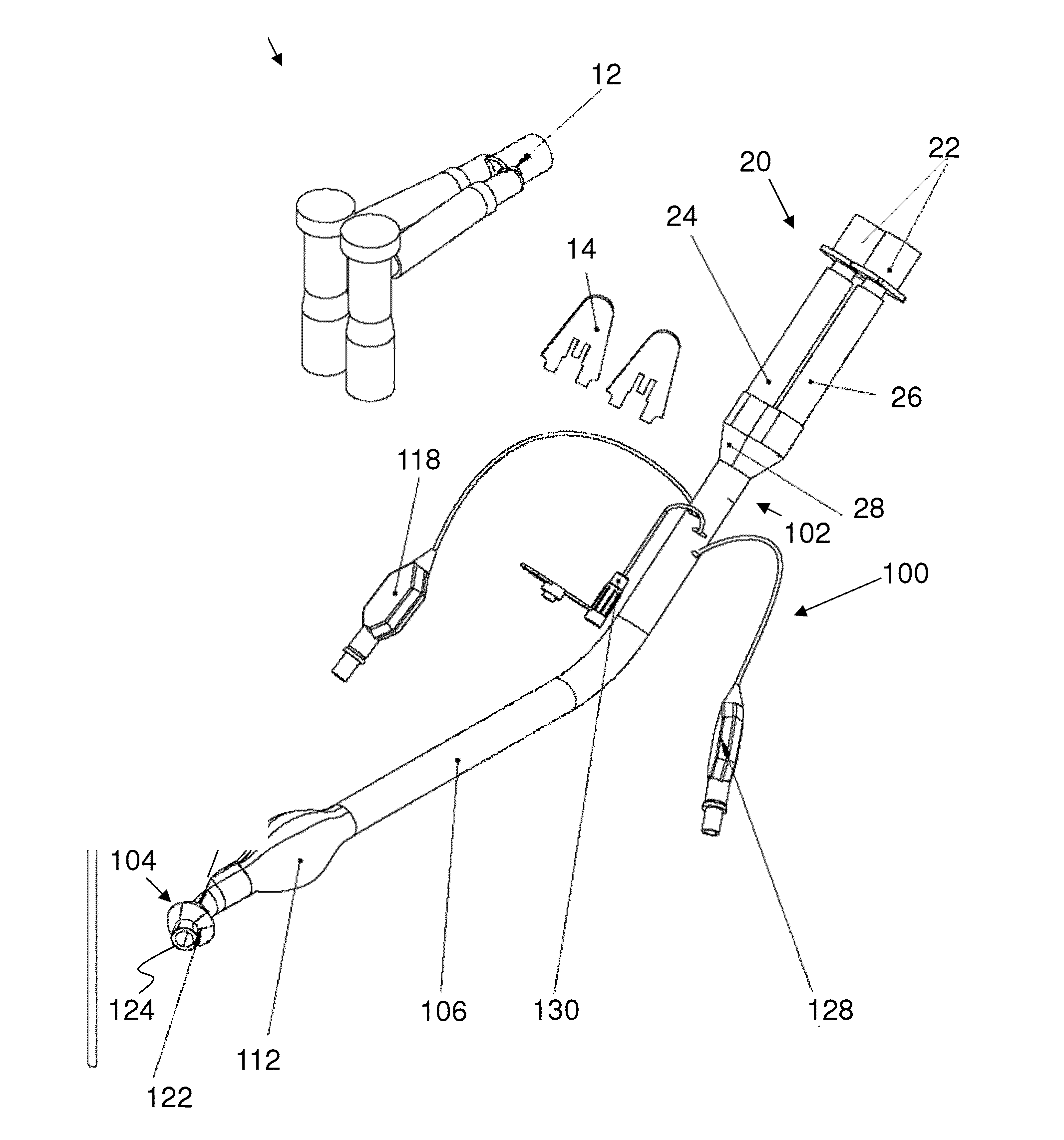
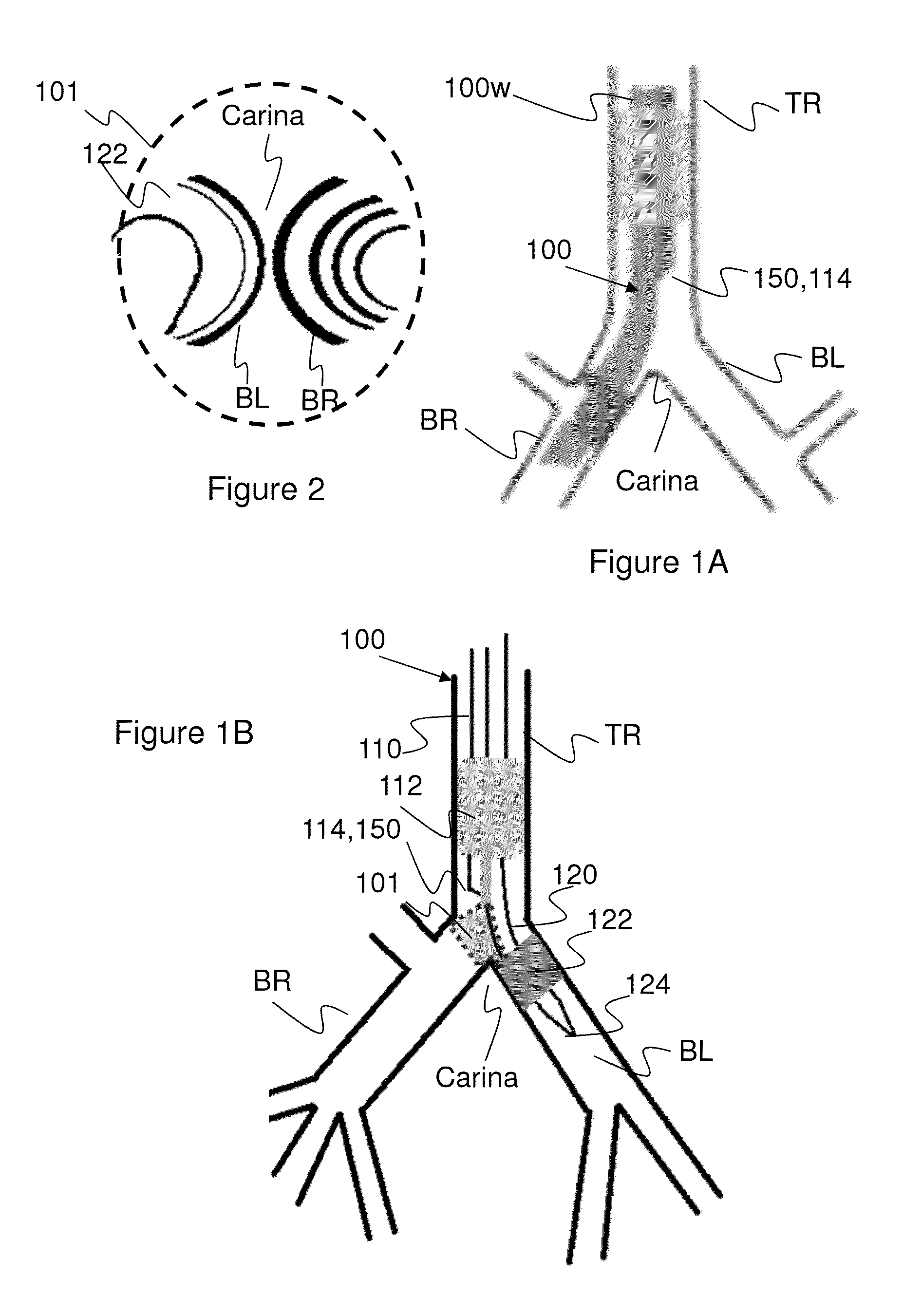
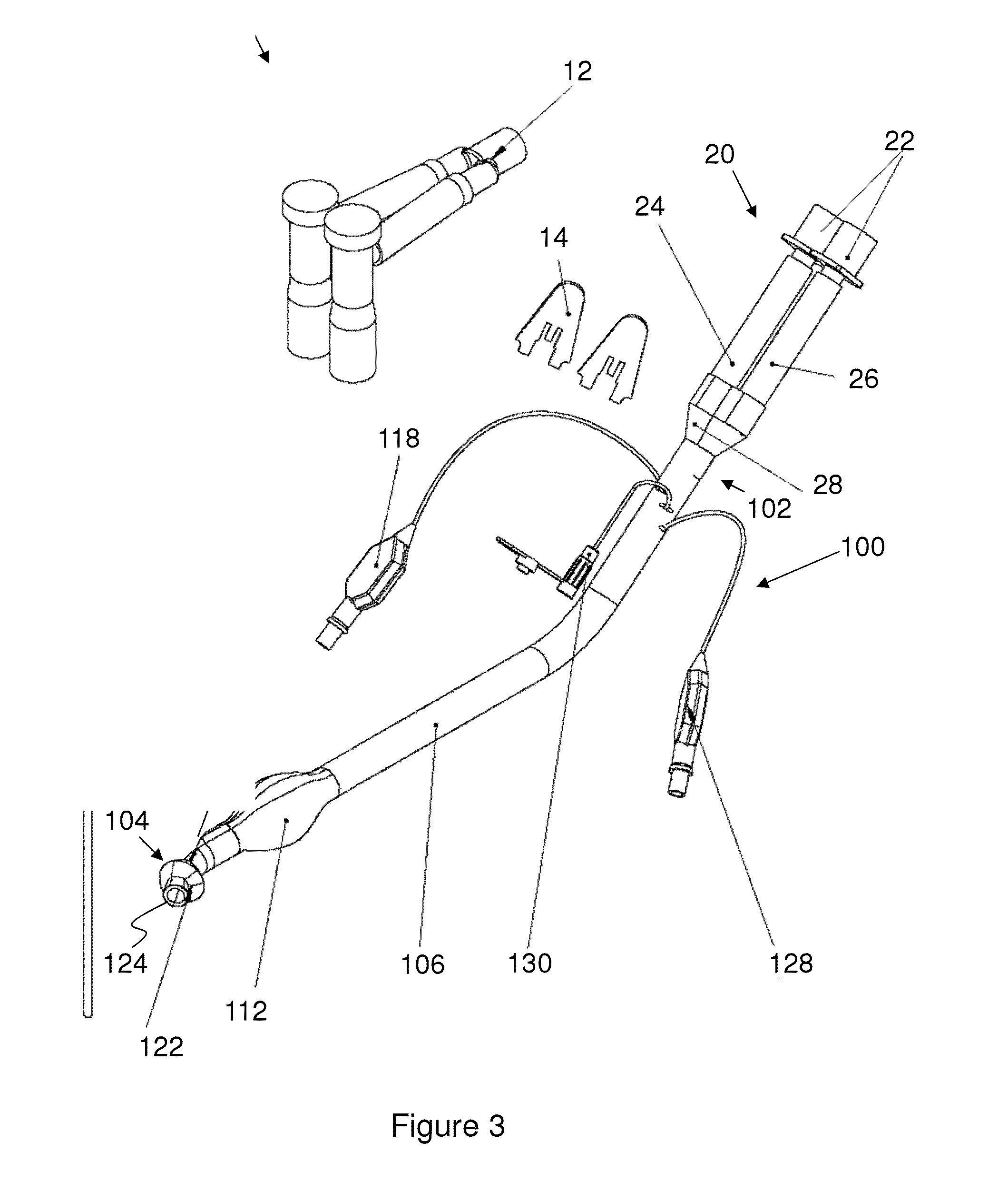
[0054]The principles and operation of the present invention may be better understood with reference to the drawings and the accompanying description. The following reference labels listed below are used throughout the drawings to refer to objects having similar function, meaning, role, or objective.[0055]Stylet;[0056]12 Y-connector;[0057]14 Air Balance Cap;[0058]20 Endobronchial Tube connector assembly;[0059]22 Endobronchial Tube connector proximal end;[0060]24 Tracheal lumen connector portion;[0061]26 Bronchial lumen connector portion;[0062]28 Endobronchial Tube connector distal end;[0063]50 endobronchial tube system;[0064]100 endobronchial tube;[0065]100w tube external wall;[0066]101 sectional view;[0067]102 tube proximal end;[0068]104 tube distal end;[0069]104a distal curvature;[0070]106 tube medial portion;[0071]106a medial curvature;[0072]108 midline partition;[0073]110 tracheal lumen;[0074]111 tracheal lumen connector;[0075]112 tracheal cuff;[0076]112n tracheal cuff notch;[007...


PUM


Abstract

An endobronchial tube which contains an integrated camera and light source and a cleaning nozzle arrangement disposed within dedicated peripheral lumen within the tube's wall.

Description

CROSS-REFERENCE TO RELATED APPLICATIONS[0001]This application is a US Continuation In Part Application of PCT Application No. PCT / IB2012 / 052077 filed on 26 Apr. 2012, which claims the benefit of U.S. Provisional Application Ser. No. 61 / 506,210 filed on 11 Jul. 2011, all of which are hereby incorporated by reference in their entirety.FIELD OF THE INVENTION[0002]The present invention relates to upper airway tubes and in particular, to an endobronchial tube with an integrated image sensor and light source having a cleaning nozzle arrangement.BACKGROUND OF THE INVENTION[0003]Respiratory tubes for example endobronchial tubes, endotracheal tubes, tracheostomy tubes are used to ventilate at least a portion of the respiratory system or lungs of a subject. Such respiratory tubes may be inserted in a number of ways via a non-invasive approach through an orifice or cavity such as the oral or nasal cavity. Alternatively such tubes may be introduced to a body via a minimally invasive external in...

Claims


Application Information

Patent Timeline
Patent Type & Authority Applications(United States)
IPC IPC(8): A61M16/04A61B1/267A61B1/12A61B1/012A61B1/06A61B1/07A61B1/313A61B1/05A61B1/00
CPCA61M16/0434A61B1/051A61B1/2676A61M16/0463A61B1/126A61B1/00082A61B1/012A61B1/0676A61B1/0684A61B1/07A61B1/313A61M16/0461A61M16/0465A61B1/00094A61B1/00091A61M15/00A61M16/04A61M16/044A61M16/0404A61M16/0459A61M16/0486A61M16/0833A61B1/00018A61B1/00124A61B1/015A61B1/05A61B1/12A61M16/0057A61M16/0488A61M16/104
Inventor DAHER, ELIAS
Owner AMBU AS
Why Eureka
Try Eureka