Phase difference layer laminated body for three dimensional liquid crystal display device and manufacturing method thereof

a technology of liquid crystal display device and laminated body, which is applied in the direction of paper/cardboard containers, instruments, photomechanical equipment, etc., can solve the problems of limited orientation of resultant phase difference films, inability to meet such demands, and inability to achieve optical compensation with conventional phase difference films, so as to achieve high molecular orientation freedom and manufacturing ease

Inactive Publication Date: 2014-02-06
DAI NIPPON PRINTING CO LTD
View PDF1 Cites 2 Cited by
  • Summary
  • Abstract
  • Description
  • Claims
  • Application Information

AI Technical Summary

Benefits of technology

[0008]The present invention has been devised in view of the above problems, and a main object thereof is to provide a phase difference layer laminated body which has very high freedom of molecular orientation in its phase difference layer and which can be manufactured with ease, a manufacturing method thereof, and a liquid crystal display device.

Problems solved by technology

However, this method only allows fabrication of phase difference films in which the main chains of polymer are oriented in the directions of stretch, and therefore the problem was that the orientation of resultant phase difference films was limited only to directions parallel to the surface of the phase difference film.
Meanwhile, phase difference films having vertical polymer orientation relative to the surface, or various other orientation directions, are now in demand; the problem with the above method for obtaining phase difference films by stretching polymer films is that it cannot meet such demand because of its little freedom in setting orientation direction.
In a multi-domain type liquid crystal display element, for example, in which each unit cell is divided into a plurality of regions with different directions of liquid crystal directors, optical compensation with the conventional phase difference film was, while favorable in some regions, not necessarily satisfactory in other regions.

Method used


Image

  • Phase difference layer laminated body for three dimensional liquid crystal display device and manufacturing method thereof
  • Phase difference layer laminated body for three dimensional liquid crystal display device and manufacturing method thereof
  • Phase difference layer laminated body for three dimensional liquid crystal display device and manufacturing method thereof

Examples


first embodiment

a. FIRST EMBODIMENT

[0063]In this embodiment, the base material itself has orientability; specifically, the base material is a stretched film. With a stretched film, the liquid crystal material can be oriented along a stretched direction of the film. Therefore, the processing of the base material is accomplished simply by preparation of a stretched film, which is a merit that the processing step is made very simple. For the stretched film, any commercially available stretched film can be used, or a stretched film can be made, according to needs, of various materials.

[0064]More specifically, examples of the film include films made of thermoplastic polymers, such as polycarbonate polymers, polyester polymers such as polyarylate or polyethylene terephthalate, polyimide polymers, polysulfone polymers, polyethersulfone polymers, polystyrene polymers, polyolefin polymers such as polyethylene or polypropylene, polyvinyl alcohol polymers, cellulose acetate polymers, polyvinyl chloride polyme...

second embodiment

b. SECOND EMBODIMENT

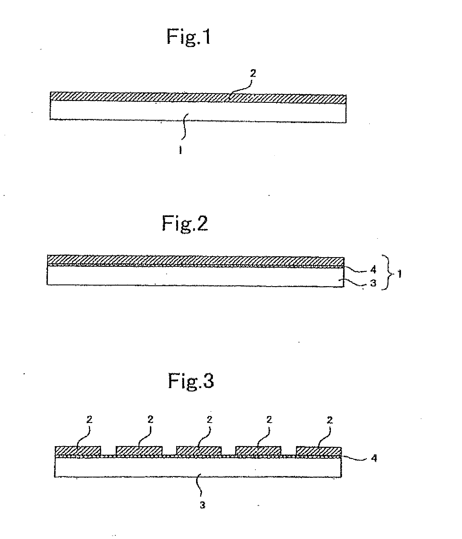
[0068]In the second embodiment, the base material having the above orientability comprises a transparent substrate and an oriented film formed thereon.

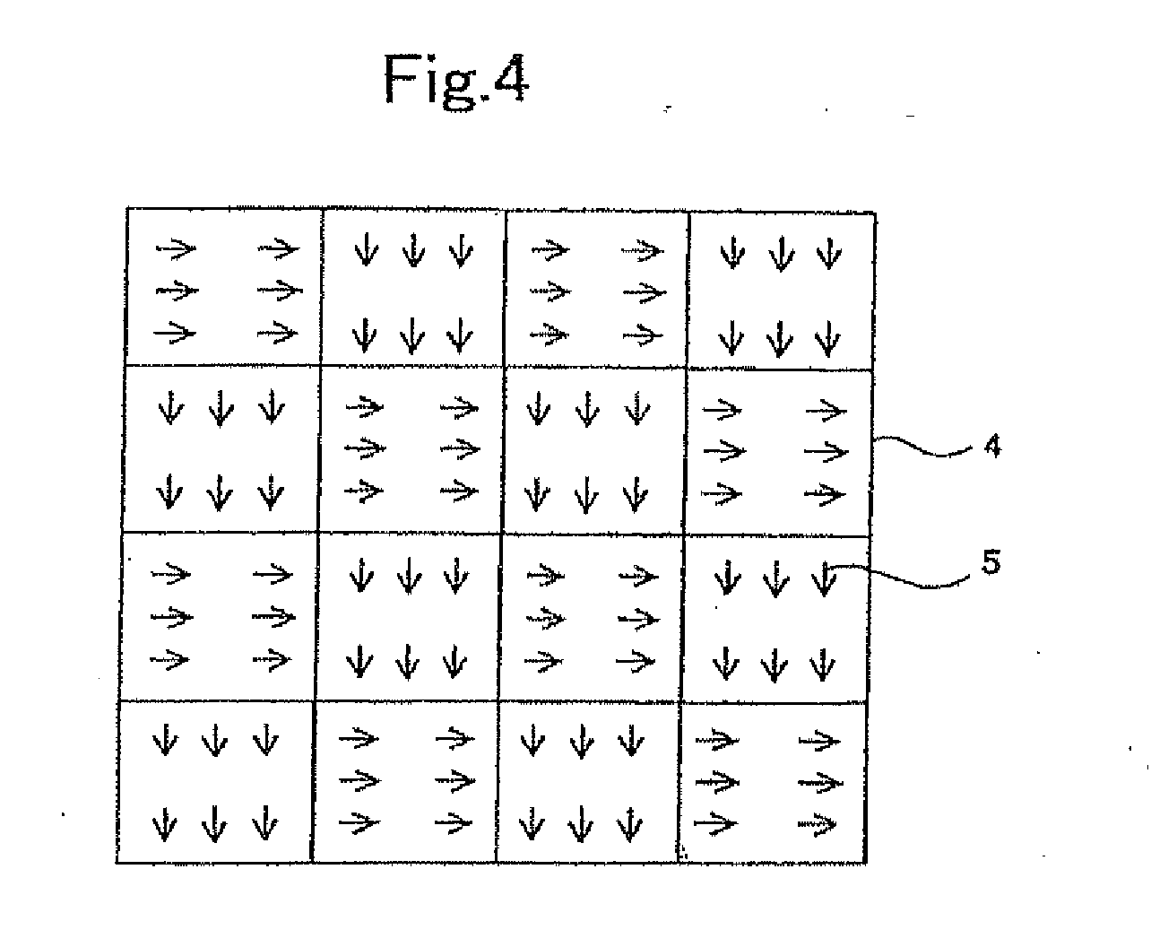
[0069]With this embodiment, there is a merit that selection of the orientated film enables selection of orientation in a relatively wider range of directions. Selecting the type of liquid applied on the transparent substrate for forming the oriented film allows orientation in various directions and enables even more effective orientation.

[0070]An oriented film commonly used for a liquid crystal display device or the like can favorably be used for the oriented film of this embodiment; generally, an oriented film of polyimide that has undergone rubbing treatment is favorably used.

[0071]For the transparent substrate used in this embodiment, any transparent material can be used, e.g., a transparent and rigid material having no flexibility such as silica glass, Pyrex (registered trademark) glass, and synthetic silica gl...

example

[0184]An example will be described below for further explanation of the invention.

[0185]A solution of polymerizable liquid crystal monomer in toluene was prepared, the monomer having a mesogen in the center, polymerizable acrylate at either end, and a spacer linking therebetween, and having a liquid crystal-isotropic transition temperature (temperature at which liquid crystal transforms into an isotropic phase) of 100.degree. C. Note that, a photopolymerization initiator (Irg 184: Ciba Specialty Chemicals Corp.) was added to the above solution in toluene in an amount of 5% by weight relative to the monomer molecules.

[0186]Meanwhile, polyimide was applied on a glass substrate to form a coat, which then underwent rubbing treatment in certain directions, to form an oriented film.

[0187]This glass substrate with the oriented film was then set in a spin coater, and the above solution in toluene was applied onto the oriented film to a thickness of about 5.mu.m by spin coating.

[0188]Next, t...


PUM

PropertyMeasurementUnit
temperatureaaaaaaaaaa

Abstract

A phase difference layer laminated body used in a three-dimensional liquid crystal display device, wherein unit cells are divided into groups for left and right eyes, which are given different degrees of polarization, thereby creating a three-dimensional image, further wherein the phase difference layer laminated body has a base material having orientability, and a phase difference layer made of a liquid crystal material that can form a nematic phase and formed in a pattern with two different portions, and the liquid crystal material in each of two different portions is oriented to have different refractive index anisotropy each other that conforms to the two different degrees of polarization and fixed as it is.

Description

[0001]This application is a Continuation-in-part of Ser. No. 13 / 954,483, filed Jul. 30, 2013 which is a Divisional of Ser. No. 13 / 728,160, filed Dec. 27, 2012 which is a Divisional of Ser. No. 12 / 923,312, filed Sep. 14, 2010, which in turn is a Continuation-in-Part of Ser. No. 12 / 073,636, filed Mar. 7, 2008, which in turn is a Continuation of Ser. No. 11 / 602,382, filed Nov. 21, 2006, which in turn is a Continuation of Ser. No. 10 / 473,215, filed Oct. 30, 2003, which in turn is a National Phase of International Patent Application No. PCT / JP02 / 11601, filed Nov. 7, 2002, which claims priority of Japanese Patent Application Nos. 2001-343873, filed Nov. 8, 2001 and 2002-259150, filed Sep. 4, 2002. The disclosures of these applications are incorporated herein by reference in their entirety.TECHNICAL FIELD[0002]The present invention relates to a phase difference layer laminated body for a three dimensional liquid crystal display device which offers high orientation freedom and allows easy p...

Claims


Application Information

Patent Timeline
Patent Type & Authority Applications(United States)
IPC IPC(8): G03F7/213B32B37/14
CPCB32B37/14G03F7/213G02F1/13363G03F7/001G02B5/201G02B5/3016G03F7/2022G03F7/26G03F7/70466G03F7/70566Y10T156/10G02B30/25G02F1/133631G02F1/133638
Inventor KASHIMA, KEIJI
Owner DAI NIPPON PRINTING CO LTD
Why Eureka
Try Eureka