

Imaging lens and imaging apparatus
an imaging lens and imaging technology, applied in the field of imaging lenses and imaging apparatuses, can solve the problems of tougher requirements for imaging lenses mounted on in-vehicle cameras, surveillance cameras or the like, and achieve the effects of low cost, wide angle of view, and small siz
- Summary
- Abstract
- Description
- Claims
- Application Information
AI Technical Summary
Benefits of technology
Problems solved by technology
Method used
Image

Examples
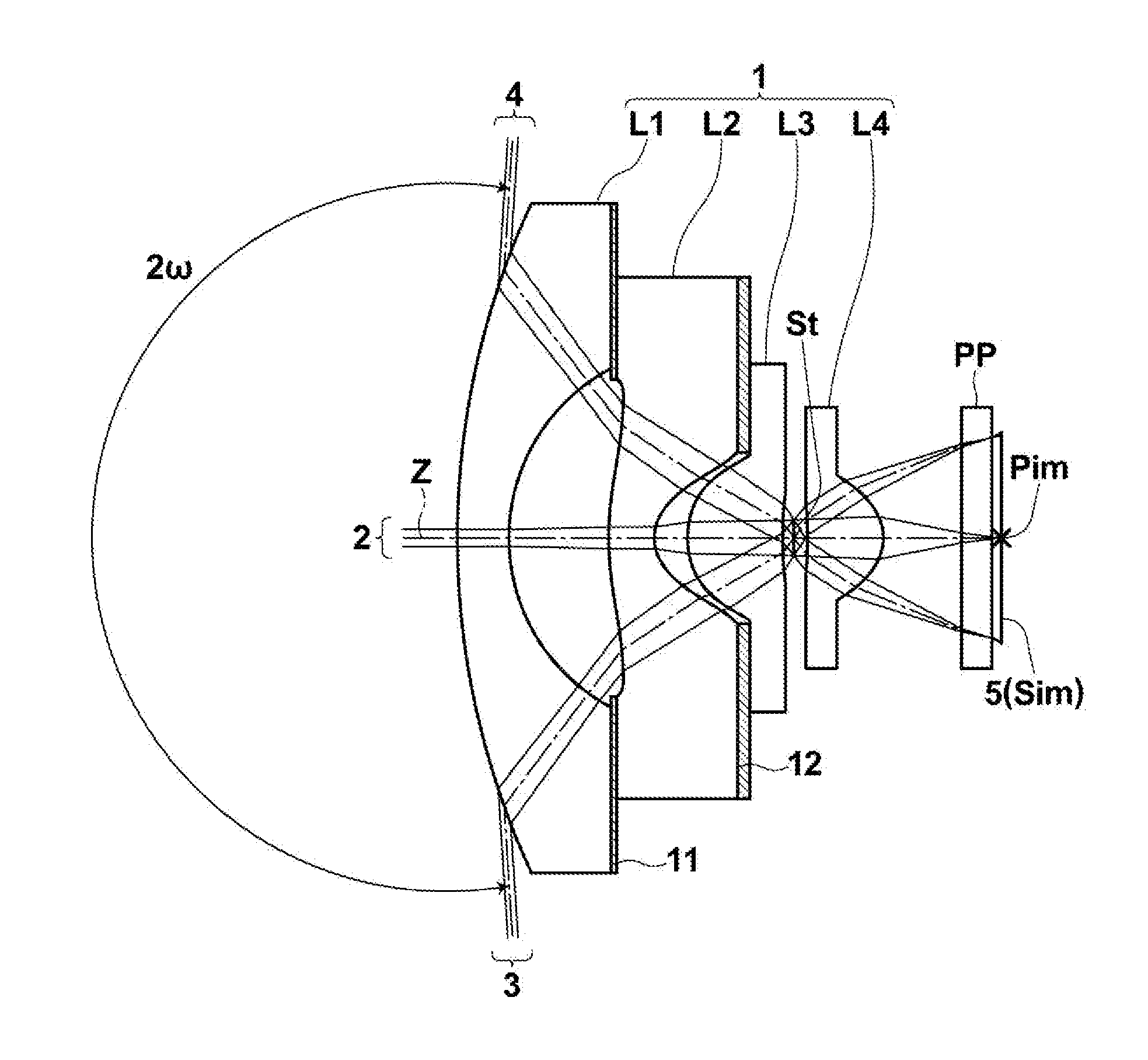
first embodiment
[0149]Further, the imaging lens according to the present invention satisfies the following conditional formula (11):
3.1<R4 / f (11),
where
[0150]R4: a curvature radius of an image-side surface of second lens L2, and
[0151]f: a focal length of an entire system.
[0152]When the lower limit of conditional formula (11) is satisfied while second lens L2 has a biconcave shape, it is possible to prevent the curvature radius of the image-side surface of second lens L2 from becoming small, and to easily correct curvature of field and a spherical aberration, or it is possible to suppress the power of second lens L2. Therefore, it is possible to prevent rays from being sharply bent by this lens, and correction of distortion becomes easy.
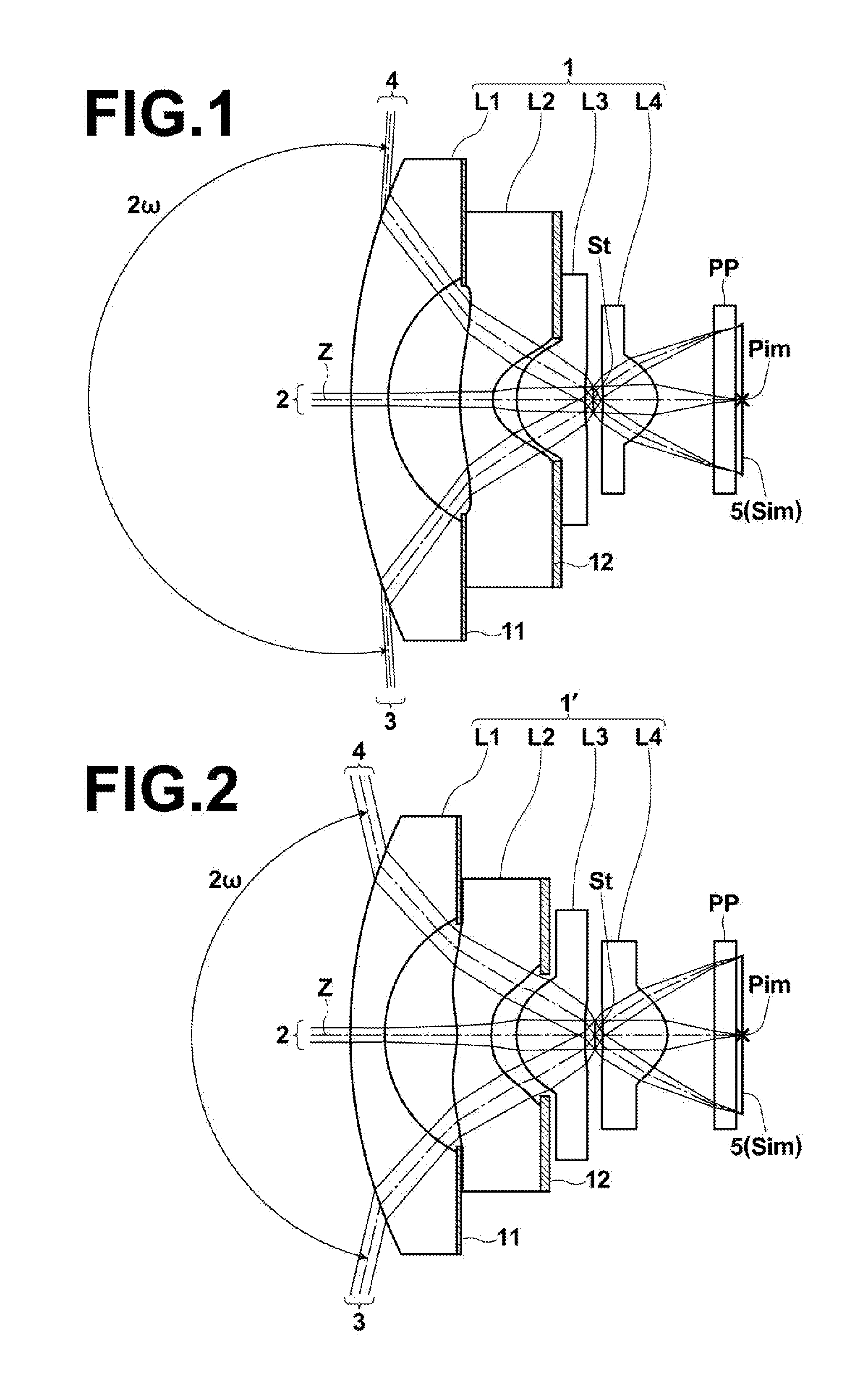
[0153]Next, the structure of a second embodiment of the present invention will be described. An imaging lens according to the second embodiment of the present invention includes negative first lens L1, second lens L2 of a negative meniscus shape having a convex su...
second embodiment
[0157]Further, the imaging lens according to the present invention satisfies the following conditional formula (11-1):
R4 / f<1.3 (11-1).
[0158]If the value exceeds the upper limit of conditional formula (11-1) while second lens L2 has a meniscus shape having a convex surface directed toward the object side, the power of second lens L2 becomes too weak, and it becomes difficult to widen an angle of view and to correct distortion.
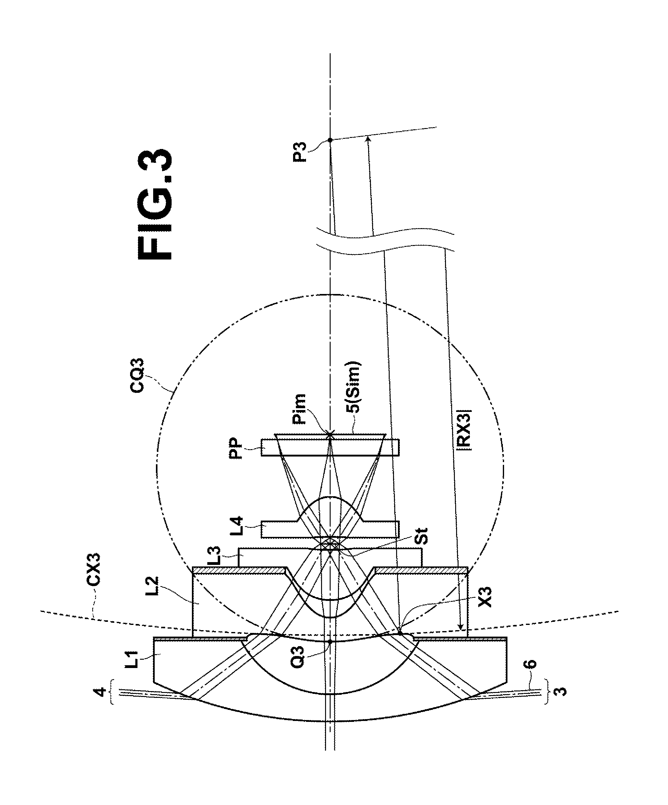
[0159]Next, the structure of a third embodiment of the present invention will be described. An imaging lens according to the third embodiment of the present invention includes negative first lens L1, negative second lens L2, third lens L3 of a plano-convex shape having a convex surface directed toward an object side or of a positive meniscus shape having a convex surface directed toward the object side, and fourth lens L4 of a plano-convex shape having a convex surface directed toward an image side or of a positive meniscus shape having a convex surface dire...
third embodiment
[0162]Further, the imaging lens according to the present invention satisfies the following conditional formula (12):
−160R3−R4) / (R3+R4)<0.85 (12),
where
[0163]R3: a curvature radius of an object-side surface of second lens L2, and
[0164]R4: a curvature radius of an image-side surface of second lens L2.
[0165]When the upper limit of conditional formula (12) is satisfied, it is possible to easily reduce the curvature radius of the object-side surface of a meniscus shape having a convex surface directed toward the object side, and to easily reduce the size of the lens system. When the lower limit of conditional formula (12) is satisfied, it is possible to easily reduce the absolute value of the curvature radius of the object-side surface of second lens L2, compared with the absolute value of the curvature radius of the image-side surface of second lens L2, in a biconcave lens. Therefore, correction of curvature of field, a coma aberration and a spherical aberration becomes easy.
[0166]Next,...
PUM
 Abstract
Description
Claims
Application Information