Fiber optic display apparatus and methods of osillating illuminated optical fibers

Active Publication Date: 2014-04-17
SPANGLER THOMAS MARK
View PDF6 Cites 3 Cited by
  • Summary
  • Abstract
  • Description
  • Claims
  • Application Information

AI Technical Summary

Benefits of technology

[0013]Another embodiment of the present invention comprises a fiber optic display comprising one or more varying length fiber optic strands, either individual or in bundles, with one end of each strand or bundle being tightly bound to a holding member, the other end of the fiber optic strand, or bundle(s), unrestrained and allowed to move freely about. The holding member contains a light source, such as a light emitting diode mounted within the holding member and oriented to expose and illuminate the bound fiber ends, causing light to be emitted from the free, unrestrained fiber ends. The holding member can be freely secured to a pivot point axis that is attached to, or part of a housing. This pivot point axis within the fiber holding member is non-parallel to the longitudinal axis of the holding member and tightly bound fibers within the holding member, and approximately perpendicular to or parallel to an imaginary line that is perpendicular to, the longitudinal axis of the tightly bound illuminated fiber ends and holding member. The fiber holding member can be functionally attached to a housing of any desired shaped in such a manner so that the holding member can move freely through its entire range of motion without restriction. The fiber holding member can further incorporate a surface or channel, shaped and positioned in such a way as to allow a rotating cam wheel to come in contact with the surface or channel, causing movement of the holding member and illuminated fibers. The

Problems solved by technology

While this axial motion of the holder and fibers can create unique visual effects, the range o

Method used


Image

  • Fiber optic display apparatus and methods of osillating illuminated optical fibers
  • Fiber optic display apparatus and methods of osillating illuminated optical fibers
  • Fiber optic display apparatus and methods of osillating illuminated optical fibers

Examples


Example

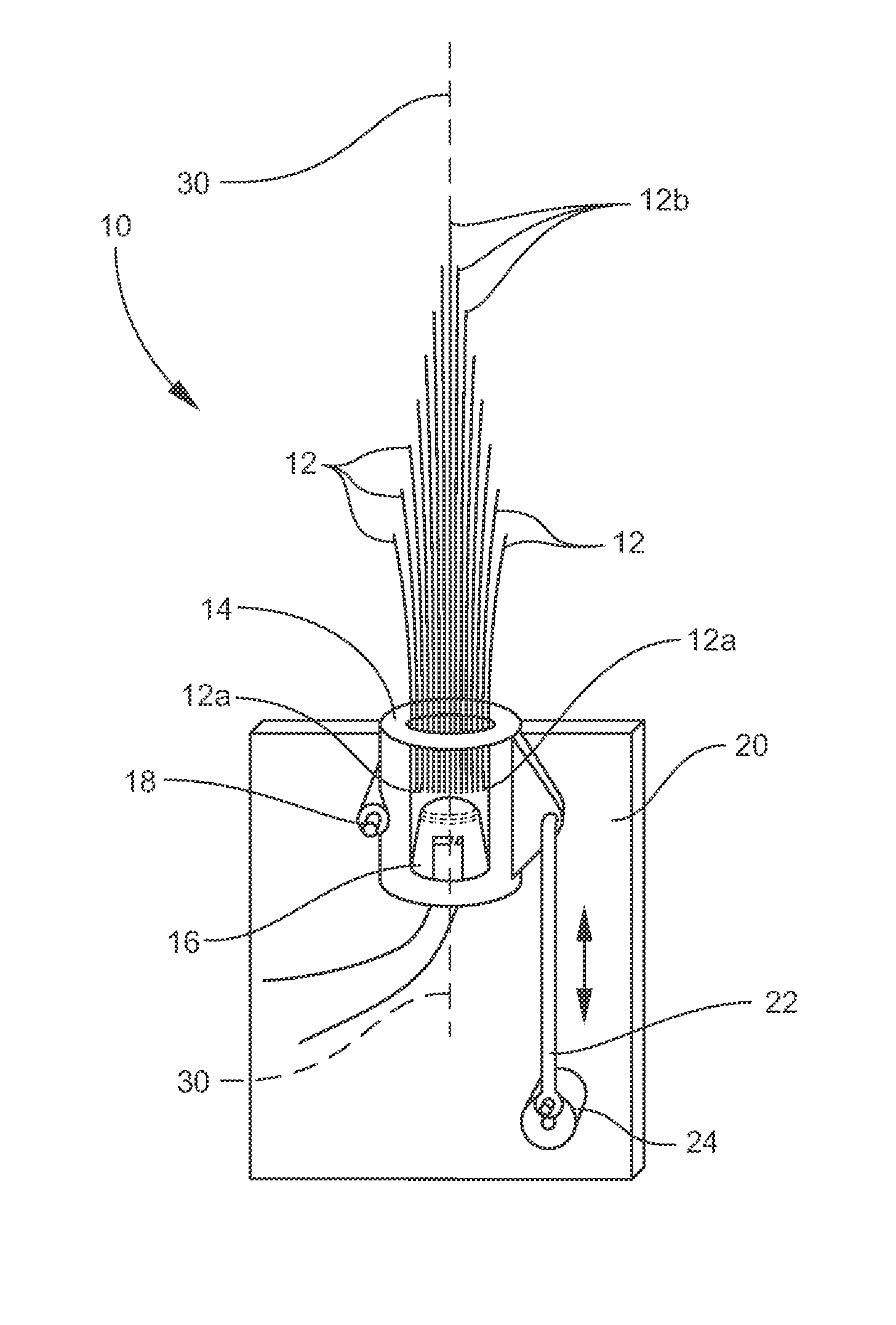
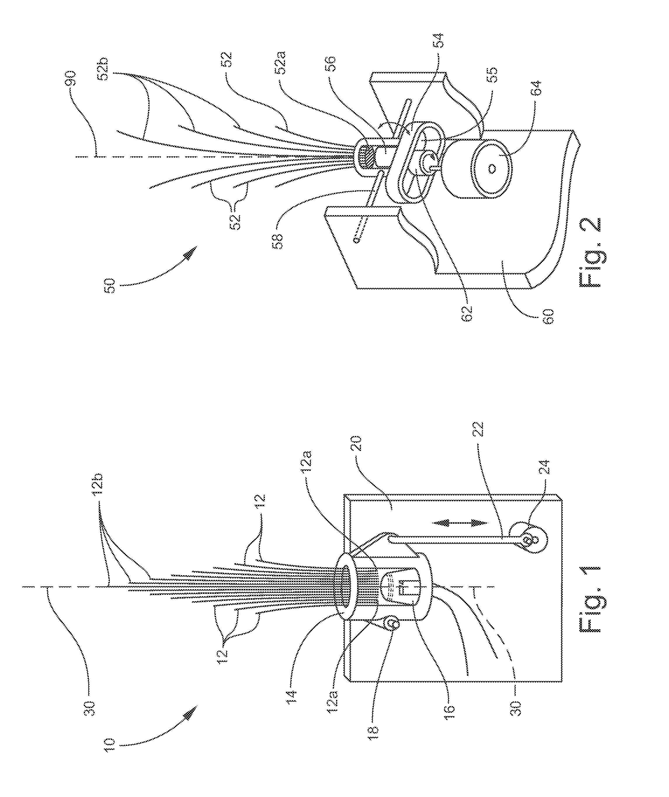
[0033]An optical fiber display device according to a preferred embodiment of the invention is illustrated in FIG. 1, and shown generally at reference numeral 10. The device 10, utilizes a locomotive-type method of oscillation and comprises varying length fiber optic strands 12 tightly bound to or within a holding member 14. The fiber strands 12 can be individually bound to the holding member 14 or bound as bundles. One end 12a of each strand 12 is bound to the holding member 14, and is referred to herein as the illuminated end 12a of the fibers 12. The other end 12b of the fiber optic strand 12 is unrestrained and allowed to move freely about, and is referred to herein as the display end 12b of the fibers 12. The holding member 14 is functionally attached to a housing 20.

[0034]In addition to the illuminated fiber ends 12a of the fibers 12, the holding member 14 contains a light source 16 to illuminate the fibers 12. The light source 16 can comprise one or more of the following: an i...


PUM


Abstract

A fiber optic display device reciprocates fiber optics to create decorative optical fiber light displays. The device can include one or more optical fibers contained at one end by a holding member and left suspended freely at the other end. The holding member and optical fibers are functionally attached about a pivot point axis that is across the longitudinal axis of the fibers and the holding member, to a housing. A light source can be affixed to either the holding member or the housing, opposite the freely suspended optical fiber ends, and is oriented to expose and illuminate the optical fibers. A drive means causes the holding member and optical fibers to reciprocate back and forth about the pivot point axis of the holding member.

Description

CROSS REFERENCE TO RELATED APPLICATIONS[0001]This application is a continuation in part of U.S. patent application Ser. No. 13 / 327,344, filed Dec. 15, 2011, which is incorporated herein and claims priority to U.S. Provisional Patent Application No. 61 / 423,572, filed Dec. 15, 2010, which is also incorporated herein.TECHNICAL FIELD AND BACKGROUND OF THE INVENTION[0002]The present invention relates to decorative fiber optic lamps, toys, and displays, and various new methods of moving and manipulating illuminated optical fibers. Fiber optics have been used for decades to create visually stimulating displays and decorations, even incorporating movement to enhance the visual effects. The type of movement has been thus far about an axis running longitudinally through the fibers within their holder. While this axial motion of the holder and fibers can create unique visual effects, the range of motion, responsiveness, and illumination options of the optical fibers is inherently limited. A ne...

Claims


Application Information

Patent Timeline
IPC IPC(8): F21V8/00
CPCG02B6/0005G09F13/18
Inventor SPANGLER, THOMAS MARK
Owner SPANGLER THOMAS MARK
Why Eureka
Try Eureka