Connector with side power bay

Active Publication Date: 2014-04-17
MOLEX INC
3 Cites 1 Cited by

AI-Extracted Technical Summary

Problems solved by technology

However, although the electrical connector assembly in the prior art is provided with the additional power supply by the receptacle power terminal 122 and the plug power terminal 152, as the second tongue plate 114 for arranging the receptacle power terminal 122 and the first tongue plate 113 are ve...

Abstract

A receptacle connector, a plug connector and an electrical connector assembly, the receptacle connector comprises a housing, a cage, a separation unit, a plurality of receptacle terminals, and a plurality of receptacle power terminals. The housing comprises a first tongue plate and a second tongue plate which are arranged transversely at an interval. The cage is installed to the housing and surrounds the first tongue plate and the second tongue plate to define a mating space. The separation unit extends into the mating space to separate the mating space into an HDMI receptacle portion and a power receptacle portion which are arranged transversely. The receptacle terminal is provided to the first tongue plate for transmitting a signal conforming to a HDMI transmission specification. The power terminal is provided to the second tongue plate for transmitting power.

Application Domain

Two-part coupling devicesCoupling protective earth/shielding arrangements

Technology Topic

EngineeringTransmitted power +2

Image

  • Connector with side power bay
  • Connector with side power bay
  • Connector with side power bay

Examples

  • Experimental program(1)

Example

[0024]The foregoing and other technical contents, features and effects of the present application will be apparent through the following detailed description for an embodiment in combination with the drawings.
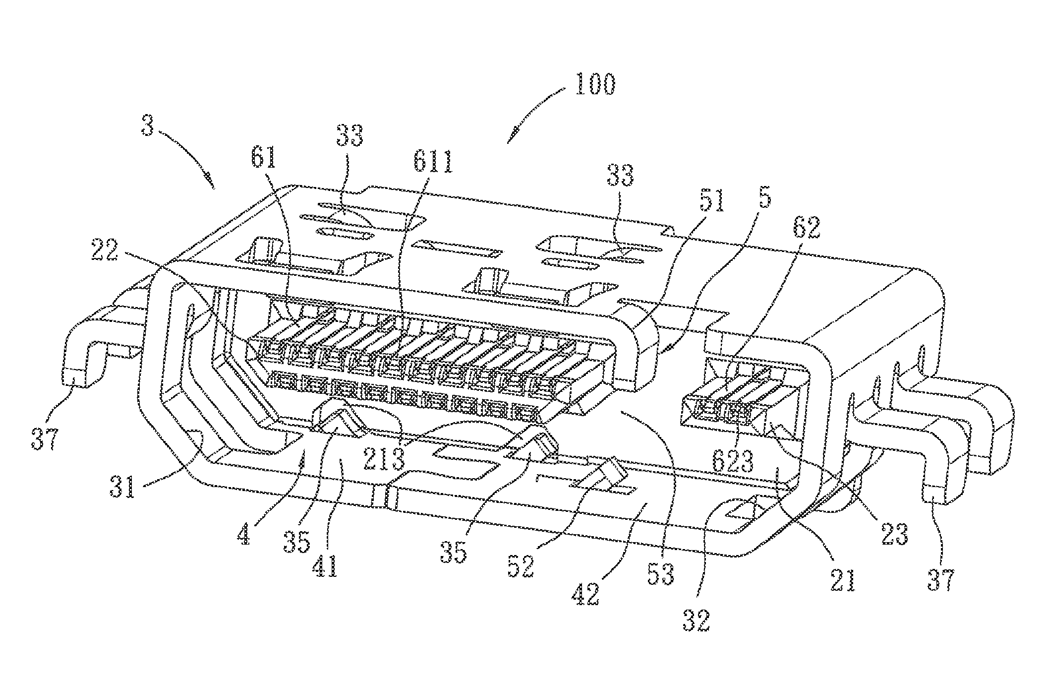
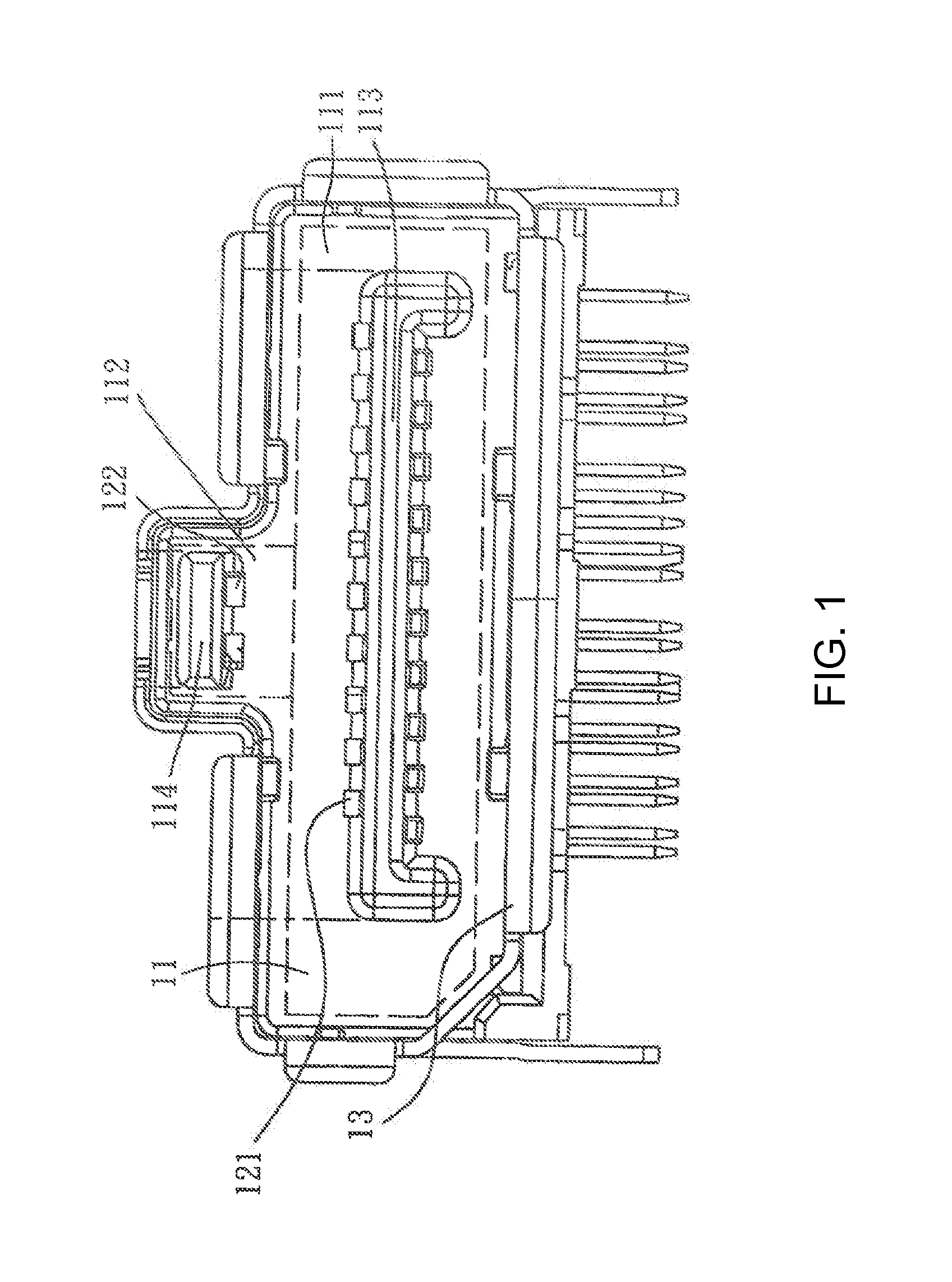
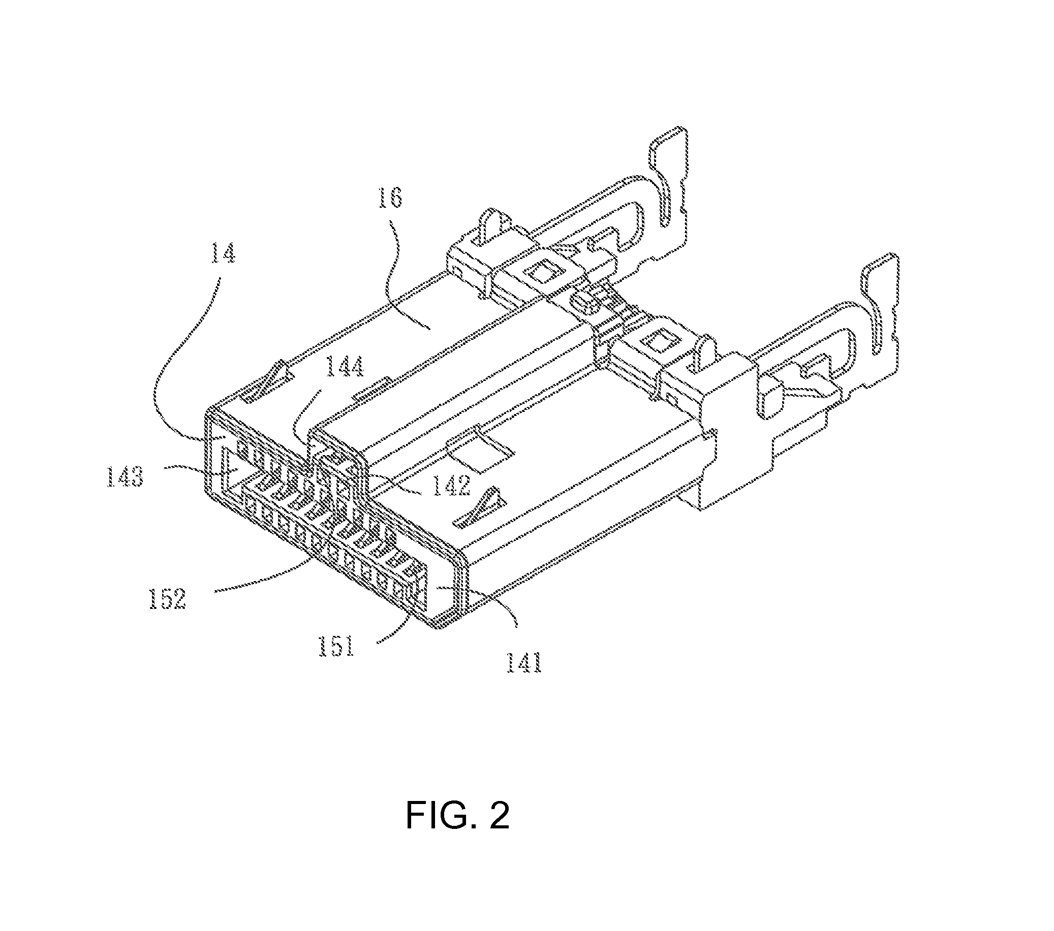
[0025]Therefore, an object of the present application is to provide a receptacle connector, a plug connector and an electrical connector assembly which can provide an additional power supply without increasing an overall height. The present application has the following effects: by that the HDMI receptacle portion and the power receptacle portion in the receptacle connector are arranged transversely relative to each other, and the HDMI plug portion and the power plug portion in the plug connector are arranged transversely relative to each other, the electrical connector assembly is provided with an additional power supply without increasing an overall height of the electrical connector assembly. In addition, by that a slot of the HDMI receptacle portion corresponds to the standard HDMI plug in shape, the receptacle connector can mate a traditional HDMI plug besides the plug connector, so that the object of the present application is reliably achieved.
[0026]An embodiment of the electrical connector assembly of the present application comprises a receptacle connector 100 (referring to FIG. 3), a plug connector 200 (referring to FIG. 6) which can be selectively inserted into the receptacle connector 100, and an HDMI plug 300 (referring to FIG. 11) which can be selectively inserted into the receptacle connector 100. High Definition Multimedia Interface is hereinafter referred to as HDMI.
[0027]Referring to FIG. 3, FIG. 4 and FIG. 5, a receptacle connector 100 in one embodiment is illustrated. The receptacle connector 100 comprises a housing 2, formed of an insulative material, a cage 3 provided to the housing 2, a separation unit 5 connected to the cage 3, a plurality of receptacle terminals 61, and a plurality of receptacle power terminals 62. The housing 2 comprises a base block 21, which can be rectangular, extending transversely, and a first tongue plate 22 and a second tongue plate 23 forwardly extending transversely from a front side face of the base block 21. The first tongue plate 22 and the second tongue plate 23 are respectively arranged transversely at an interval. The cage 3 surrounds the first tongue plate 22 and the second tongue plate 23 to define a mating space 4.
[0028]The separation unit 5 is positioned in the mating space 4 to separate the mating space 4 into an HDMI receptacle portion 41 and a power receptacle portion 42 which are respectively arranged transversely, and comprises a first separation plate 51 and a second separation plate 52 respectively extending from two opposite faces of the cage 3 toward the mating space 4, and a communication space 53 positioned between the first separation plate 51 and the second separation plate 52 to communicate the HDMI receptacle portion 41 and the power receptacle portion 42. In one embodiment, the first separation plate51 extends from a top wall of the cage 3 toward the mating space 4, the second separation plate 52 extends from a bottom wall of the cage 3 relative to the first separation plate 51 toward the mating space 4. The first tongue plate 22 is positioned in the HDMI receptacle portion 41, and the second tongue plate 23 is positioned in the power receptacle portion 42. A contact portion 611 of each receptacle terminals 61 is provided to the first tongue plate 22 for transmitting a signal conforming to a HDMI transmission specification. A contact portion 623 of each receptacle power terminals 62 is provided to the second tongue plate 23 for transmitting power. Wherein, in one embodiment the plurality of receptacle power terminals 62 comprise a positive terminal 621 and a negative terminal 622, other terminals can be additionally provided in a varied embodiment for power supplies with different voltage combinations.
[0029]The base block 21 is further provided with a recessed portion 211 positioned in a rear side, a first fixing groove 212 positioned in a front side of the top of the base block 21, and two second fixing grooves 213 positioned in a front side of the bottom of the base block 21. The cage 3 further comprises a plurality of bent hooks 33 extending into the recessed portion 211 and tightly latching both sides of a rear end of the base block 21, a fixing portion 34 inwardly protruding to extend into the first fixing groove 212, and two fixing pieces 35 oppositely protruding inwardly from the cage 3 to extend into the second fixing grooves 213. By that the fixing portion 34 and the fixing pieces 35 both tightly abut the front side of the base block 21, and the plurality of bent hooks 33 tightly latch the rear side of the base block 21, the cage 3 is constrained relative to the base block 21 in the front-back direction. The top wall of the cage 3 is provided with two leaf springs 36, and two side faces of the cage 3 have a plurality of retaining leg portions 37 for being fixed or soldered to a circuit board (not shown).
[0030]Referring to FIG. 6, FIG. 7 and FIG. 8, an embodiment of a plug connector 200 is illustrated. The plug connector 200 comprises a plug housing 7, a terminal module 80 provided to the plug housing 7, and a plug cage 9 installed to the plug housing 7. The plug housing 7 comprises a base portion 71, which can be rectangular, extending transversely, a plug structure 72 forwardly extending transversely from a front side face of the base portion 71, and a separation portion 73. An end of the plug structure 72 is provided with an HDMI plug portion 721 and a power plug portion 722 respectively arranged transversely at an interval. The separation portion 73 is positioned between the HDMI plug portion 721 and the power plug portion 722 to separate the HDMI plug portion 721 and the power plug portion 722. The HDMI plug portion 721 and the power plug portion 722 respectively define an HDMI slot 723 and a power slot 724 therein.
[0031]The terminal module 80 comprises a plurality of plug terminals 81 and a plurality of plug power terminals 82. The plurality of plug terminals 81 each have a contact portion 811 positioned in the HDMI slot 723, and the plurality of plug terminals 81 can be electrically connected to the plurality of receptacle terminals 61 (see FIG. 5) so as to transmit the signal conforming to the HDMI transmission specification. The plurality of plug power terminals 82 each have a contact portion 821 received in the power slot 724, and the plurality of plug power terminals 82 can be electrically connected to the plurality of receptacle power terminals 62 (see FIG. 5) so as to transmit power. The plug cage 9 comprises a collar 91 fixed to the base portion 71, a shielding sheath 92 extending forwardly from the collar 91 and surrounding and covering the plug structure 72, and two fixed hooks 93 oppositely extending inwardly from two opposite sides of the collar 91. The plurality of fixed hooks 93 match with each other to clamp the base portion 71, so as to allow the plug cage 9 and the base portion 71 to be firmly fixed to each other.
[0032]The separation portion 73 has a connection plate 731 transversely connecting the HDMI plug portion 721 and the power plug portion 722, a first recessed groove 732 positioned in one side of the connection plate 731, and a second recessed groove 733 positioned in the other side of the connection plate 731. Further in combination with referring to FIG. 5, a shape of the connection plate 731 matches with the communication space 53 so as to be received in the communication space 53. The first recessed groove 732 can receive the first separation plate 51, and the second recessed groove 733 can receive the second separation plate 52. The shielding sheath 92 of the plug cage 9 are provided with a first cutout 921 having a shape matching with the first recessed groove 732 to allow the first separation plate 51 to pass through and a second cutout 922 having a shape matching with the second recessed groove 733 to allow the second separation plate 52 to pass through, respectively, at positions corresponding to the first recessed groove 732 and the second recessed groove 733, a top face of the shielding sheath 92 has two concave portions 923 which can be latched by the two leaf springs 36 in the top wall of the cage 3 of the receptacle connector 100.
[0033]The plug housing 7 further has an assembling space 76 communicating the HDMI slot 723 and the power slot 724, and an upper clamping plate 74 and a lower clamping plate 75 which extend rearwardly from a rear side of the base portion 71. The terminal module 80 further comprises a first frame 77 and a second frame 78 which are secured to each other. A surface of the first frame 77 is provided with a plurality of first latch portions 771. The second frame 78 is provided with a plurality of second latch portions 781 at positions corresponding to the plurality of first latch portions 771 so as to be engaged with the plurality of first latch portions 771. In one embodiment, the first latch portion 771 and the second latch portion 781 are respectively a through hole and a post, but configurations of the first latch portion 771 and the second latch portion 781 are not limited to that, as long as the first frame 77 and the second frame 78 can be fixed to each other. The plurality of plug terminals 81 are divided into two groups which are embedded and fixed respectively in the first frame 77 and the second frame 78. The plurality of plug power terminals 82 are partially embedded and fixed in the first frame 77 and spaced from the plurality of plug terminals 81. The first frame 77 and the second frame 78 latch with each other and then are inserted into the assembling space 76 in the plug housing 7, and are fixed to the plug housing 7 by that protruding blocks 772 respectively formed in the first frame 77 and the second frame 78 and catching grooves 741 respectively formed in the upper clamping plate 74 and the lower clamping plate 75 latch with each other.
[0034]Referring to FIG. 3, FIG. 6, FIG. 9 and FIG. 10, when the receptacle connector 100 and the plug connector 200 are mated, the plug structure 72 of the plug connector 200 together with the shielding sheath 92 covering the plug structure 72 are inserted into the mating space 4 of the receptacle connector 100, so that the HDMI plug portion 721 and the power plug portion 722 of the plug structure 72 are received in the HDMI receptacle portion 41 and the power receptacle portion 42 of the mating space 4, respectively, and the connection plate 731 of the plug connector 200 is received in the communication space 53 of the receptacle connector 100. At this time, the first tongue plate 22 is inserted into the HDMI slot 723 so as to electrically connect the plurality of plug terminals 81 and the plurality of receptacle terminals 61 and transmit a signal conforming to the HDMI transmission specification. In the meantime, the second tongue plate 2 is inserted into the power slot 724 so as to electrically connect the plurality of plug power terminals 82 and the plurality of receptacle power terminals 62 and transmit power.
[0035]In addition, the cage 3 of the receptacle connector 100 is provided with an HDMI receptacle oblique corner 31 and a power receptacle oblique corner 32 at corners defining the HDMI receptacle portion 41 and the power receptacle portion 42, respectively, and the second separation plate 52 of the receptacle connector 100 extends obliquely from the cage 3 at an angle symmetrically to an angle of the HDMI receptacle oblique corner 31, and the first separation plate 51 of the receptacle connector 100 extends vertically from an inner face of the cage 3. Moreover, a corner of the HDMI plug portion 721 adjacent to the second recessed groove 733 and a corner thereof far away from the second recessed groove 733 are respectively provided with oblique corners 725, the plurality of oblique corners 725 are symmetrical to each other. And a corner of the power plug portion 722 far away from the second recessed groove 733 is provided with an oblique corner 726. The oblique angles of the oblique corner 31 and the second separation plate 52 described above and the oblique angles of the oblique corners 725 correspond to each other, while the oblique angle of the oblique corner 32 and the oblique angle of the oblique corner 726 correspond to each other. By such a design that the oblique angles correspond to each other, incorrect insertion in a wrong direction can be prevented when a user inserts the plug structure 72 into the mating space 4, and a smooth guiding is provided for the plug structure 72 while inserting and the receptacle connector 100 and the plug connector 200 are further secured once the plug structure 72 is inserted.
[0036]Referring to FIGS. 11-14, a HDMI plug 300 of one embodiment is illustrated, the HDMI plug 300 is a plug conforming to the HDMI specification, and is for being inserted into the HDMI receptacle portion 41 of the receptacle connector 100. The HDMI plug 300 comprises an plug housing 7′, a terminal module 80′ assembled into the plug housing 7′ of the HDMI plug 300, and a cage 9′ installed to the plug housing 7′ of the HDMI plug 300. The plug housing 7′ of the HDMI plug 300 comprises a base portion 71′ extending transversely, and an HDMI plug portion 72′ outwardly extends transversely from a side face of the base portion 71′ of the HDMI plug 300. The HDMI plug portion 72′ of the HDMI plug 300 can be inserted into the HDMI receptacle portion 41 (see FIG. 5) via a matched shape thereof, and defines a terminal slot 74′ therein. The terminal module 80′ of the HDMI plug 300 comprises a plurality of terminals 8′ each of which extends into the terminal slot 74′ at one end, the plurality of terminals 8′ can be electrically connected with the plurality of receptacle terminals 61 so as to transmit the signal conforming to the HDMI transmission specification. The cage 9′ of the HDMI plug 300 comprises a collar 91′ fixed to the base portion 71′ of the HDMI plug 300, and a shielding sheath 92′ extending forwardly from the collar 91′ of the HDMI plug 300 and surrounding the HDMI plug portion 72′ of the HDMI plug 300. The shielding sheath 92′ of the HDMI plug 300 covers the HDMI plug portion 72′ of the HDMI plug 300, so as to provide an additional protection for the HDMI plug portion 72′ of the HDMI plug 300.
[0037]When the receptacle connector 100 and the HDMI plug 300 are mated, the HDMI plug portion 72′ of the HDMI plug 300 together with the shielding sheath 92′ covering the plug structure 72′ are inserted into the HDMI receptacle portion 41 of the receptacle connector 100 so as to electrically connect the plurality of terminals 8′ and the plurality of receptacle terminals 61 and transmit the signal conforming to the HDMI transmission specification. It should be noted that, two corners of the HDMI plug portion 72′ of the HDMI plug 300 are formed as two oblique corners symmetrical to each other. The oblique angles of the oblique corners as described above corresponds to the oblique angles of the HDMI receptacle oblique corner 31 and the second separation plate 52. By that incorrect insertion in a wrong direction is prevented when the user mates the HDMI plug 300 and the receptacle connector 100, and in the meantime a smooth guiding is provided for the HDMI plug portion 72′ of the HDMI plug 300, and the fixed effect of the receptacle connector 100 and the HDMI plug 300 is improved after the HDMI plug portion 72′ of the HDMI plug 300 is inserted.
[0038]In conclusion, the receptacle connector 100 divides the mating space 4 into the HDMI receptacle portion 41 and the power receptacle portion 42 which are respectively arranged transversely via the separation unit 5, so as to provide additional power supply for the receptacle connector 100 without increasing the overall height, and meet the requirement to be mounted in thin-type electronic equipment. And the separation portion 73 of the plug connector 200 divides the plug structure 72 into the HDMI plug portion 721 and the power plug portion 722, so as to provide additional power supply for the plug connector 200 without increasing the overall height. In addition, by that the oblique angles of the HDMI receptacle oblique corner 31 and the second separation plate 52 correspond to the HDMI plug oblique corners 725, incorrect insertion in a wrong direction can be prevented and a smooth guiding is provided when the user inserts the plug structure 72 into the mating space 4. Furthermore, the HDMI receptacle portion 41 of the receptacle connector 100 allows the standard HDMI plug 300 to be inserted via the matched shape, the receptacle connector 100 can be connected to the traditional HDMI plug 300 besides the plug connector 200, so that the object of the present application can be reliably achieved.
[0039]However, as described above is only embodiments of the present application, the implementation scope of the present application is not limited to that, that is , simple equivalent variations and modifications which are made according to the Claims and the description content of the present application are included in the protective scope of the present application.

PUM

no PUM

Description & Claims & Application Information

We can also present the details of the Description, Claims and Application information to help users get a comprehensive understanding of the technical details of the patent, such as background art, summary of invention, brief description of drawings, description of embodiments, and other original content. On the other hand, users can also determine the specific scope of protection of the technology through the list of claims; as well as understand the changes in the life cycle of the technology with the presentation of the patent timeline. Login to view more.
Why Eureka
Try Eureka