Dual sim card connector

a dual-sim card and connector technology, applied in the direction of coupling device connection, sensing record carrier, instruments, etc., can solve the problem of occupying a substantial amount of volume in the configuration

Active Publication Date: 2014-04-24
MOLEX INC
View PDF32 Cites 50 Cited by
  • Summary
  • Abstract
  • Description
  • Claims
  • Application Information

AI Technical Summary

Benefits of technology

[0009]The connector module further may comprise a detect switch which comprises a detect terminal and a detect piece. The detect terminal has a resilient arm, a pushed portion formed to the resilient arm, a contact portion formed to the resilient arm, and a connecting portion. The detect piece is formed to the metal cover and corresponds to the contact portion of the detect terminal. The metal cover and the connecting portion of the detect terminal are electrically connected with a detect circuit of the circuit board. The pushed portion of the detect terminal extends into the insertion space without external force and is withdrawn from the insertion space when being pushed; the contact portion is moved together with the pushed portion, and a state of electrical connection between the contact portion and the detect piece is changed when the pushed portion is withdrawn from the insertion space, thereby controlling signal transmission of the first terminals and the second terminals.

Problems solved by technology

As can be appreciated, such a configuration occupies a substantial amount of volume.

Method used


Image

  • Dual sim card connector
  • Dual sim card connector
  • Dual sim card connector

Examples


first embodiment

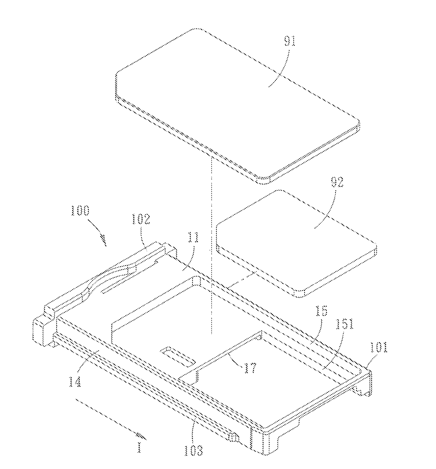
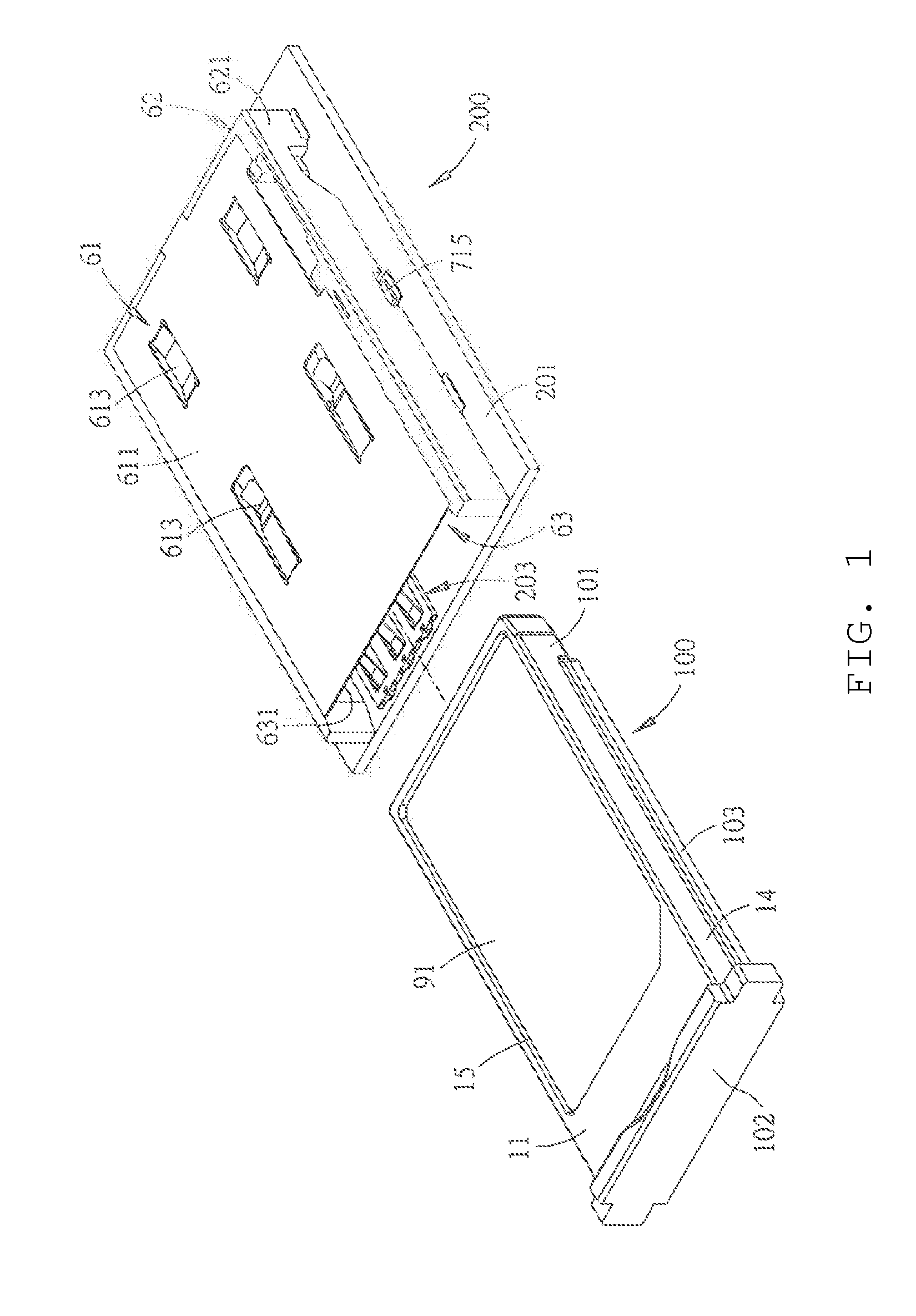
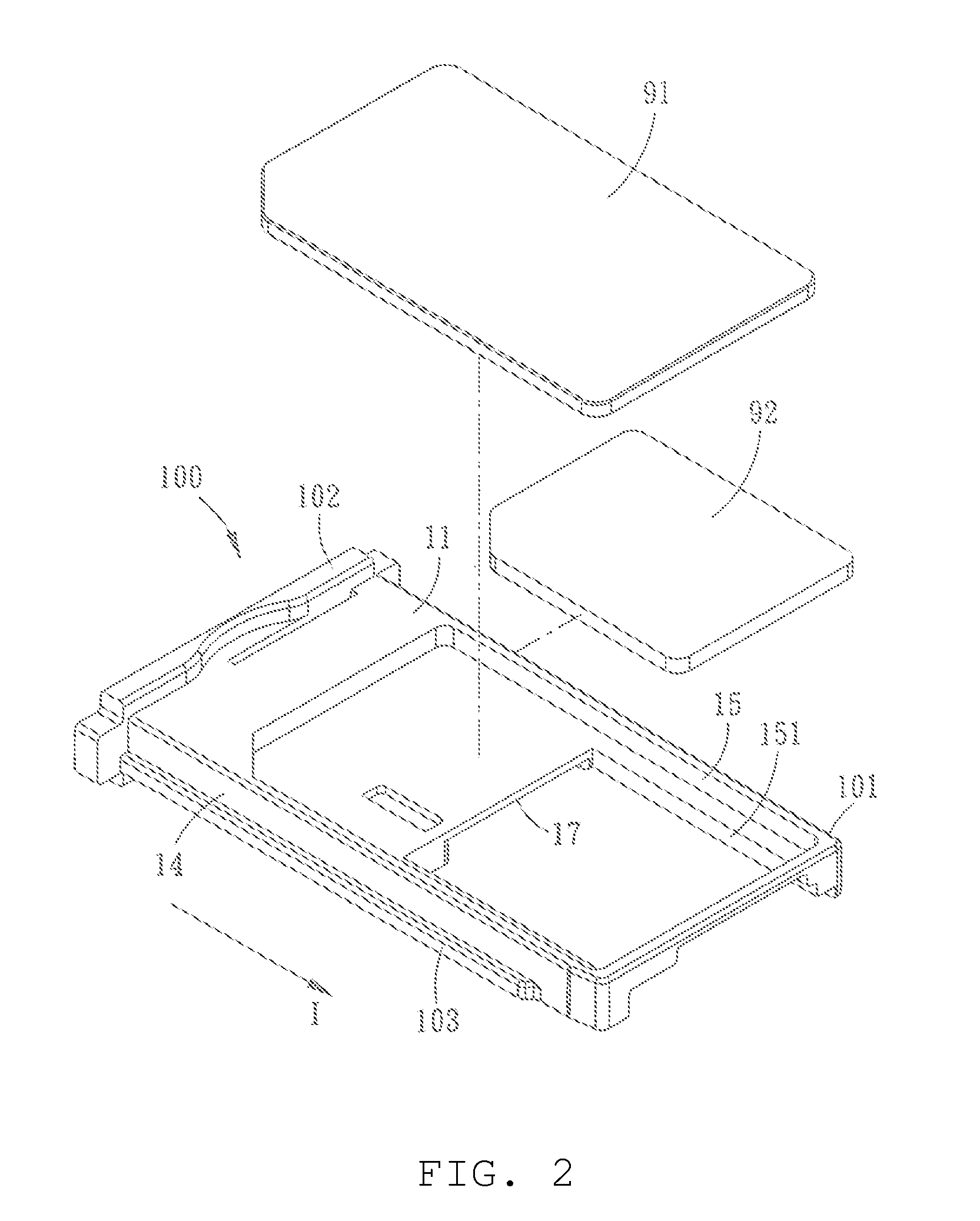
[0033]Referring to FIG. 1 and FIG. 2, an electrical connector device that is applicable to load a mini-SIM card 91 and a micro-SIM card 92 and the embodiment comprises a tray 100 and a connector module 200.

[0034]Referring to FIG. 2, FIG. 3 and FIG. 4, the tray 100 comprises a main body 101, a hand-gripping portion 102 and a polarizing portion 103. The main body 101 has a top side 11, a bottom side 12, a first side surface 13, a second side surface 14, a first receiving groove 15, a second receiving groove 16, a first window 151, a second window 161 and a spacer 17. The bottom side 12 is positioned at an opposing side of the top side 11; the first side surface 13 and the second side surface 14 are respectively connected to the top side 11 at two opposing sides and the bottom side 12 at two opposing sides and are parallel to a lengthwise direction I of the tray 100. The first receiving groove 15 for loading the mini-SIM card 91 is formed to the top side 11 of the main body 101; and th...

second embodiment

[0046]In the second embodiment, referring to FIG. 16, the tray 100 does not have a polarizing portion 103 (referring to FIG. 2); referring to FIG. 17, FIG. 18 and FIG. 19, a plane where the supporting plate 18 is present is opposite to and apart from a plane where the spacer 17 is present, and an edge of the supporting plate 18 defines one side of the second window 161. Furthermore, a notch 19′ is formed by recessing inwardly from the first side surface 13 of the main body 101 toward the supporting plate 18 at an opposing side of the supporting plate 18 so as to provide a space for a finger to insert, therefore it is convenient to take out or put in the micro-SIM card 92; and a guide slope surface 121 is formed adjacent to the second window 161, as shown in FIG. 18, the micro-SIM card 92 may be obliquely placed into the second receiving groove 16 from the second window 161, so that one side of the micro-SIM card 92 firstly enters into a region between the spacer 17 and the supportin...


PUM


Abstract

A dual SIM card tray and an electrical connector device are disclosed. The electrical connector device comprises a tray and a connector module. The dual SIM card tray has a first receiving groove and a second receiving groove, which are positioned at two opposing sides, for respectively loading a mini-SIM card and a micro-SIM card, and has a first window communicated with the first receiving groove and a second window communicated with the second receiving groove. The first window and the second window are arranged in a lengthwise direction of the tray, so that conductive pads of the two SIM cards are exposed toward the same side. The connector module includes first and second connectors and an outer shell.

Description

RELATED APPLICATIONS[0001]This application claims priority to Chinese Application No. 201210079256.7, filed Mar. 16, 2012, which is incorporated herein by reference in its entirety.FIELD OF THE PRESENT INVENTION[0002]The present application relates to an electrical connector, and more specifically, to an electrical connector suitable for use in loading SIM (Subscriber Identity Module) cards by a tray.BACKGROUND OF THE PRESENT INVENTION[0003]A conventional dual SIM card connector is configured to provide two connectors side-by-side in a left-right direction or stacked in an up-down direction so that each connector can receive one SIM card. As can be appreciated, such a configuration occupies a substantial amount of volume. Other connectors that load a SIM card by a tray can only load one SIM card and generally cannot load two SIM cards at the same time.[0004]For example, a connector loading a MMC card and a Micro-SIM card by a tray is disclosed by U.S. Pat. No. 6,568,960 (correspondi...

Claims


Application Information

Patent Timeline
Patent Type & Authority Applications(United States)
IPC IPC(8): H01R12/71
CPCH01R12/71G06K7/0039H01R27/00
Inventor LIM, KIAN HENGZENG, SHANG-XIUWANG, HONG LIANG
Owner MOLEX INC
Why Eureka
Try Eureka