Corrugated tube clamp

a technology of corrugated tubes and clamps, which is applied in the direction of machine supports, transportation and packaging, and other domestic objects, can solve the problems that corrugated tubes b>205/b> cannot be maintained in a predetermined attached position on the vehicle body panel, and corrugated tubes b>206/b> cannot be maintained in a predetermined attached position

Inactive Publication Date: 2014-06-05
DAIWA KASEI IND CO LTD
View PDF2 Cites 42 Cited by
  • Summary
  • Abstract
  • Description
  • Claims
  • Application Information

AI Technical Summary

Benefits of technology

The corrugated tube clamp described in this patent text can stabilize the corrugated tubes by using a reaction force from the biasing member, preventing them from tilting or displacing easily. This clamp can also prevent the corrugated tubes from rattling or moving between the fixed and movable portions.

Problems solved by technology

This means that the corrugated tube 205 cannot be maintained in a predetermined attached position on the vehicle body panel.
This means that the corrugated tube 206 cannot be maintained in a predetermined attached position on the vehicle body panel.

Method used


Image

  • Corrugated tube clamp
  • Corrugated tube clamp
  • Corrugated tube clamp

Examples


first embodiment

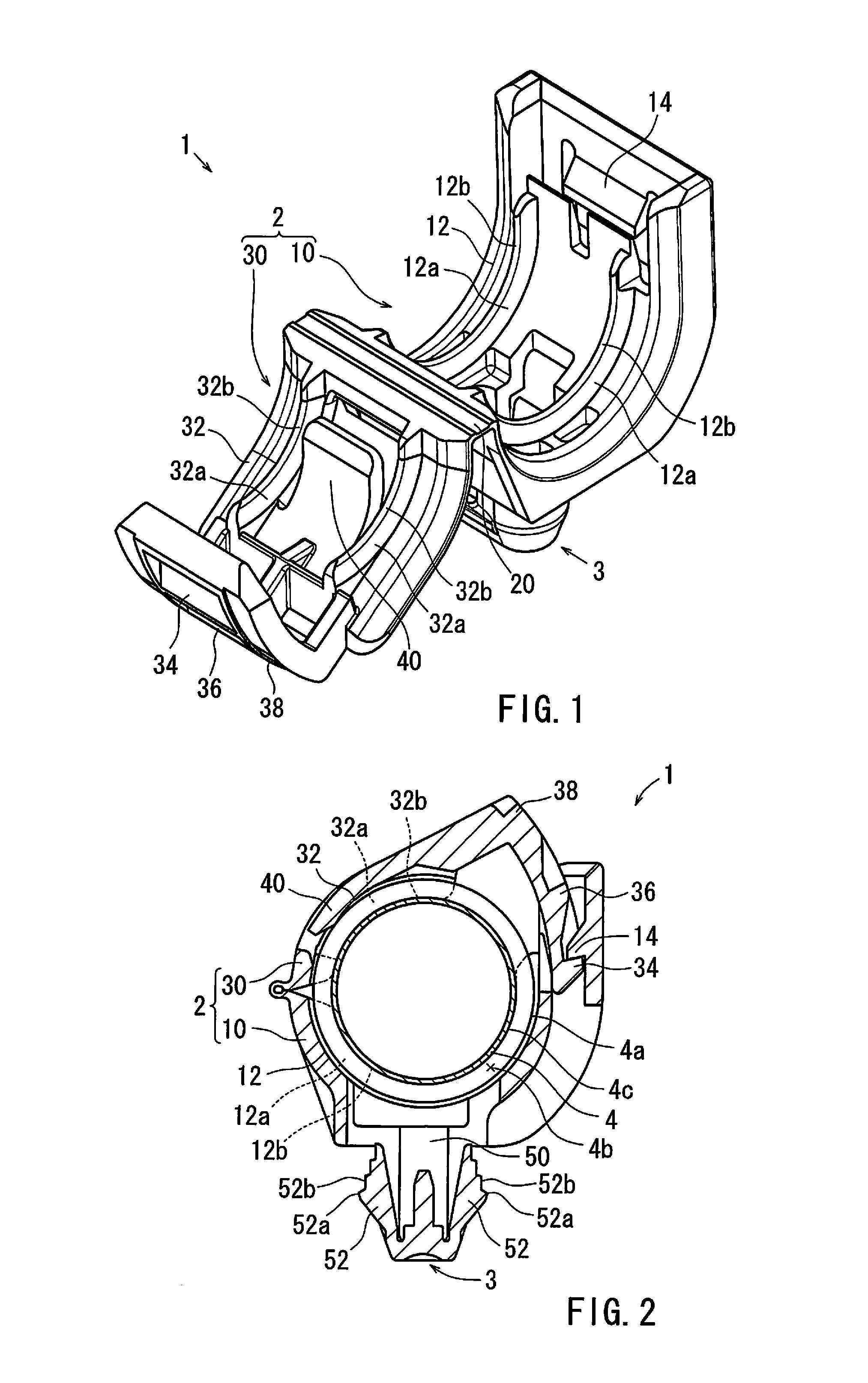
[0029]A first detailed representative embodiment of the present invention will be described with reference to FIGS. 1 to 6.

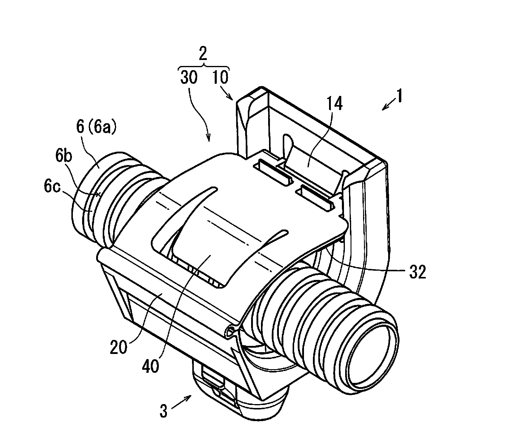
[0030]The present embodiment is directed to a corrugated tube clamp 1 that is used to attach each of corrugated tubes 4, 5 and 6 into which wiring harnesses (not shown) are respectively inserted to an attaching object, e.g., a vehicle body panel (not shown). The clamp 1 may preferably be integrally formed of rigid synthetic resin.

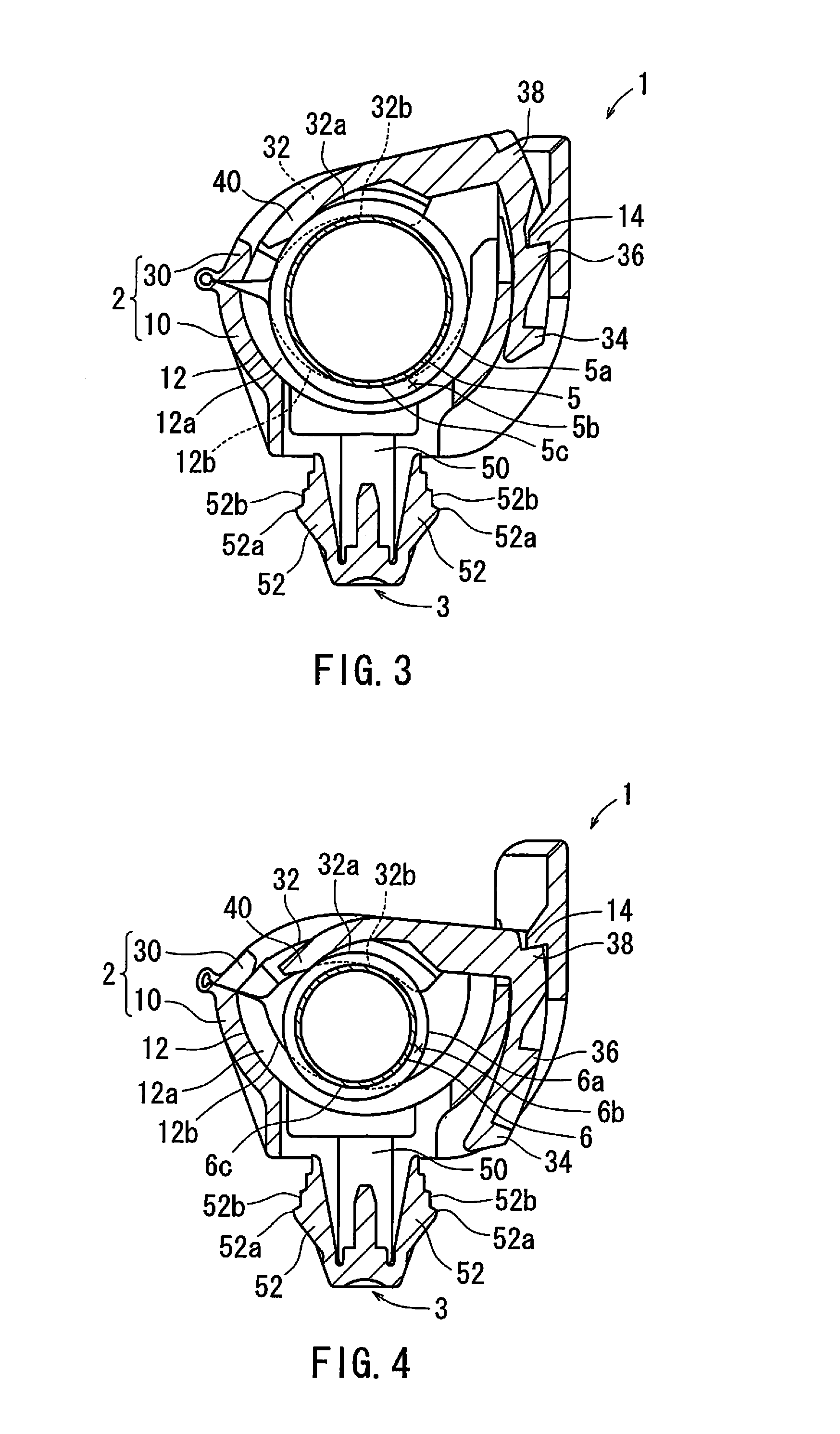
[0031]In this embodiment, the corrugated tubes 4, 5 and 6 may respectively have the substantially same structures with the exception of their diameters. For the purpose of explanation, the corrugated tubes 4, 5 and 6 may respectively be referred to as a large (largest) diameter corrugated tube, a middle diameter corrugated tube and a small (smallest) diameter corrugated tube. As shown in FIG. 2, the large diameter corrugated tube 4 may have annular grooves 4b that are circumferentially formed in an outer circumferential surface 4a there...

second embodiment

[0060]The second detailed representative embodiment will now be described with reference to FIG. 7.

[0061]Because the second embodiment relates to the first embodiment, only the constructions and elements that are different from the first embodiment will be explained in detail. Elements that are the same in the first and second embodiments will be identified by the same reference numerals and a detailed description of such elements may be omitted.

[0062]In this embodiment, similar to the first embodiment, a corrugated tube clamp 101 may have the substantially same structure as the corrugated tube clamp 1 of the first embodiment with the exception of the biasing member 40. That is, similar to the corrugated tube clamp 1 of the first embodiment, the corrugated tube clamp 101 may include the tube clamping body 2 and the attachment leg or anchor 3. The tube clamping body 2 may have the fixed portion 10 and the movable portion 30. However, unlike the first embodiment, the movable portion 3...


PUM


Abstract

A corrugated tube clamp may includes a fixed portion capable of being connected to an attaching object, a movable portion hinged to the fixed portion, ribs respectively formed in the fixed portion and the movable portion, and at least one biasing member formed in at least one of the fixed portion and the movable portion. The fixed portion and the movable portion are shaped to clamp and hold each of corrugated tubes having different diameters therebetween. The ribs are respectively shaped to engage grooves formed in an outer circumferential surface of each of the corrugated tubes of different diameters. The at least one biasing member is shaped to be pressed back by an outer circumferential surface of at least the corrugated tube with the smallest diameter when it is clamped between the fixed portion and the movable portion.

Description

BACKGROUND OF THE INVENTION[0001]1. Field of the Invention[0002]The present invention relates to a corrugated tube clamp that is used to attach a corrugated tube to a plate-shaped attaching object (e.g., a vehicle body panel). More specifically, the present invention relates to a corrugated tube clamp that is applicable to various corrugated tubes respectively having different diameters.[0003]2. Description of Related Art[0004]A corrugated tube clamp that is used to attach a corrugated tube into which a wiring harness is inserted to a vehicle body panel is already known. Such a corrugated tube clamp is taught by, for example, Japanese Laid-Open Patent Publication Number 2007-143309. As shown in FIG. 8, a corrugated tube clamp 201 taught therein includes a tube clamping body 202 that is essentially composed of a fixed portion 210 and a movable portion 230. The fixed portion 210 and the movable portion 230 are shaped to clamp each of corrugated tubes 204, 205 and 206 having different ...

Claims


Application Information

Patent Timeline
IPC IPC(8): F16L3/08
CPCF16L3/08B60R16/0215F16L3/1025F16L3/1041F16L3/1075H02G3/34H02G3/0468H02G3/32
Inventor ASAI, OSAMU
Owner DAIWA KASEI IND CO LTD
Why Eureka
Try Eureka