Control unit and method for lighting control

a control unit and lighting technology, applied in the direction of lighting devices, lighting sources, electrical devices, etc., can solve the problems of inconvenient manual operation to switch on or off each one of the plurality of lamps, inconvenient manual operation, undesired lighting control, etc., to achieve suitable/convenient lighting, not convenient to set for the target(s), and suitable/convenient lighting

Active Publication Date: 2014-06-12
KONINKLIJKE PHILIPS ELECTRONICS NV
View PDF8 Cites 53 Cited by
  • Summary
  • Abstract
  • Description
  • Claims
  • Application Information

AI Technical Summary

Benefits of technology

[0012]An advantage of the present invention is that the control unit provides a lighting which is more suitable / convenient for a target compared to the lighting obtained by other prior art systems. As the control unit of the present invention is able to estimate a 3D location of a target, the lighting function of a light source may be adapted dependent on the estimated 3D location of the target such that a more suitable / convenient lighting is provided in the space.
[0013]It will be appreciated that the inventors have realized that a control unit and a method may be provided to control luminance in a space with respect to a 3D location of a target as a function of time. The present invention is advantageous in that it conveniently provides a control / adaptation of the lighting dependent on the estimated 3D location of the target(s). In contrast, prior art systems, based on e.g. presence detection of a person in a room, may adjust the light only when presence of a person is sensed. However, these systems are inferior to the present invention, e.g. in that the systems do not set the light based on any knowledge of any position in three dimensions of the person or a portion of the person (target) as a function of time. The prior art systems are thereby related to numerous drawbacks, e.g. in that the lighting is not conveniently set for the target(s) and / or that the lighting is not energy efficient. Conversely, the control unit and the method of the present invention are highly advantageous in that they efficiently and conveniently control the luminance in the space based on an estimated 3D location of target(s) as a function of time.
[0014]As the 3D location of the target(s) is (are) estimated as a function of time, the present invention is further advantageous in that a vertical motion / movement of the target may be estimated. More specifically, a velocity and / or acceleration of the target may be estimated. Based on this information, the control of the luminance in the space may be even more improved.
[0015]It will be appreciated that the term “three-dimensional location” (3D) in this context may be construed as a spatial location, e.g. a location in a space defined by substantially any coordinate system, e.g. polar or Cartesian coordinates. Furthermore, it will be appreciated that the term “estimate” in this context may be construed as “measure”, “determine”, “predict”, or any other similar term. For example, the control unit may comprise means for sensing (e.g. a sensor) a 3D location of a target.
[0016]According to an embodiment of the present invention, the control unit may further be configured to estimate the three-dimensional location based on an azimuth angle, an elevation angle, and a distance to the target. Hence, the 3D location of the target(s) may be based on polar coordinates and a distance to the target. The present embodiment is advantageous in that the control unit hereby may conveniently estimate the spatial / 3D location of the targets(s) as a function of time.
[0017]According to an embodiment of the present invention, the control unit may further be configured to identify an activity of the target based on the estimate of the three-dimensional location and to control the luminance in the space based on the activity of the target. It will be appreciated that the terms “identify an activity” may be construed as a recognition of a pattern / scheme of the 3D location and / or 3D movement of the target(s) such that an activity of the target(s) may be identified. The present embodiment is advantageous in that the control unit firstly identifies an activity of the target (based on the 3D location(s) of the target(s) as a function of time), and secondly controls the luminance in accordance with this activity, such that the luminance is suitably / conveniently adapted to the kind of activity. Hence, the luminance offers improved visual conditions based on the activity the target is engaged in. For example, the control unit may be configured to identify a first activity based on one or more 3D locations / movements of one or more targets at a first period of time and / or at a first portion of the space, and control the luminance according to this activity. Analogously, a second activity of the target(s) may be identified at a second period of time and / or at a second portion of the space, etc., such that the control unit adapts the luminance accordingly.

Problems solved by technology

However, manual control of the lighting may at the same time be undesired, inefficient and / or tedious.
A manual operation to switch on or off each one of the plurality of lamps may in this case be inconvenient.

Method used


Image

  • Control unit and method for lighting control
  • Control unit and method for lighting control
  • Control unit and method for lighting control

Examples


Embodiment Construction

[0036]In the following description, the present invention is described with reference to a control unit controlling luminance in a space and a lighting control system for controlling a lighting function of a light source.

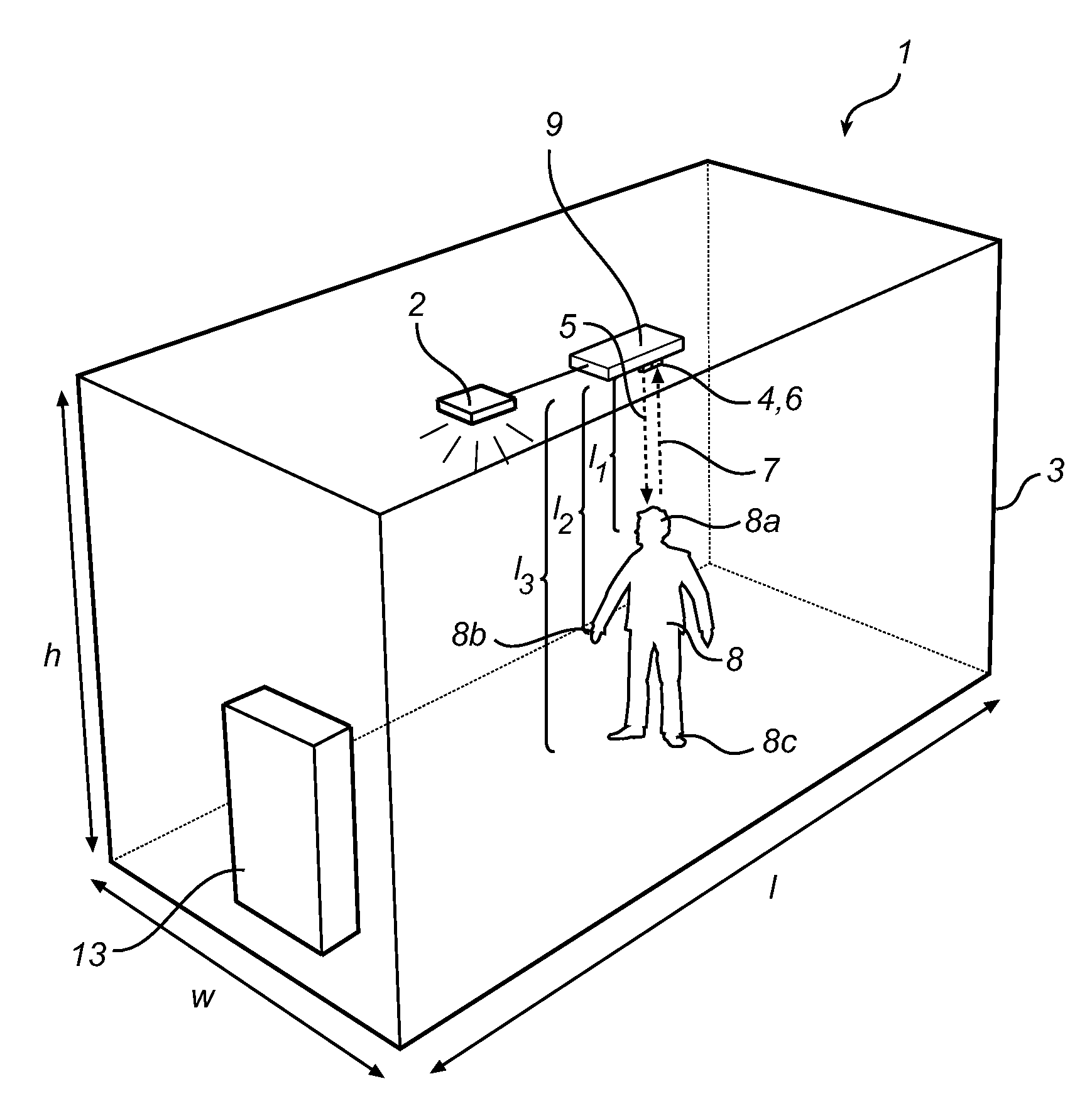
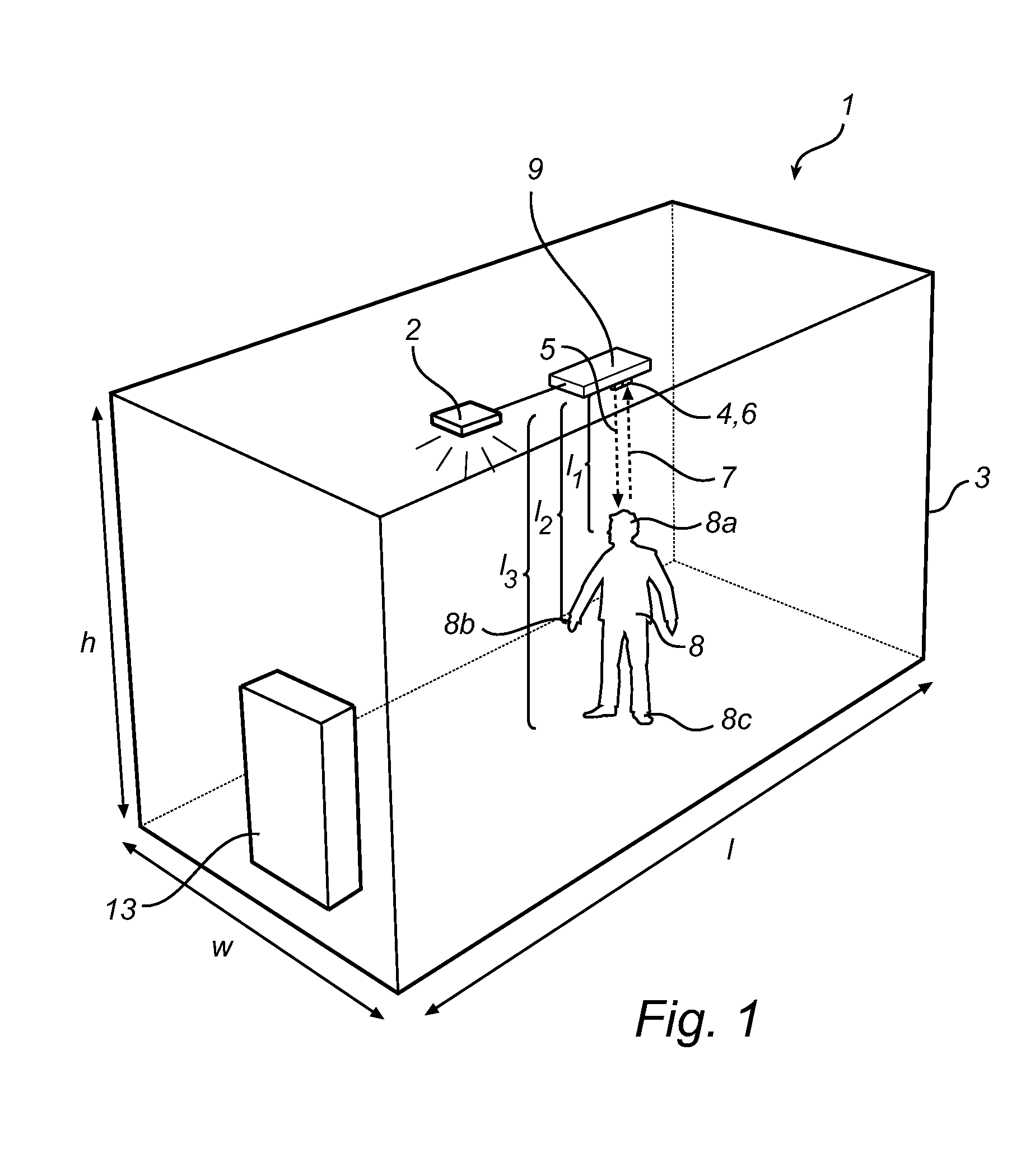
[0037]FIG. 1 is a schematic illustration of a lighting control system 1 for controlling a lighting function of an illumination device 2. Here, the space 3 is exemplified as a room 3 with length 1, width w and height h, and the illumination device 2 is shown as a single light source 2 positioned in the ceiling of the room 3. However, it will be appreciated that the illumination device 2 may comprise a plurality of light sources 2 which further may be distributed within the space / room 3.

[0038]A control unit 9 is arranged in the space 3 for controlling the luminance, wherein the control unit 9 is further configured to estimate a three-dimensional (3D) location (l1-3) of the respective targets 8a-c (in the following, the 3D locations will be indicated in the figures as ...


PUM


Abstract

A control unit (9) for controlling luminance in a space (3), wherein the control unit is configured to estimate a three-dimensional location of at least one target (8) as a function of time, and control the luminance in the space based on the estimated three-dimensional location of the at least one target.

Description

FIELD OF THE INVENTION[0001]The present invention relates to a control unit and a method for lighting control.BACKGROUND OF THE INVENTION[0002]The use of artificial lighting to achieve practical or aesthetic effects is continuously increasing. Both for indoor and outdoor settings, there are numerous examples of lighting systems including e.g. light bulbs, LEDs, and spot lights for offices, restaurants, museums, advertising boards, homes, shops, shop windows, and so on.[0003]A suitable / convenient lighting, whether in an indoor or outdoor setting, is highly beneficial for a person present in that environment, as the lighting may e.g. contribute to his / her comfort, productivity, well-being, etc. Manual control of the light source may improve the lighting, e.g. in that a person may control the lighting in a room according to his / her preference. For example, the person may switch on the light upon arrival and switch off the light when leaving the room. However, manual control of the ligh...

Claims


Application Information

Patent Timeline
Patent Type & Authority Applications(United States)
IPC IPC(8): H05B37/02
CPCH05B37/0227H05B47/115Y02B20/40
Inventor PANDHARIPANDE, ASHISH VIJAYCAICEDO FERNANDEZ, DAVID RICARDO
Owner KONINKLIJKE PHILIPS ELECTRONICS NV
Why Eureka
Try Eureka