Server cabinet

a server cabinet and cabinet body technology, applied in the field of server cabinets, can solve problems such as damage and tilting of the back end of the switch

Inactive Publication Date: 2014-07-03
CLOUD NETWORK TECH SINGAPORE PTE LTD
View PDF7 Cites 2 Cited by
  • Summary
  • Abstract
  • Description
  • Claims
  • Application Information

AI Technical Summary

Benefits of technology

The present patent relates to a server cabinet and aims to solve the problem of a long and heavy switch tilting and damaging the bonding by screws between the switch and the cabinet. The technical effect of the patent is to provide a solution to prevent damage to the switch and improve the stability of the server cabinet.

Problems solved by technology

However, if the switch is long and heavy, a rear end of the switch may tilt and damage the bonding by screws between the front end of the switch unit and the cabinet.

Method used


Image

  • Server cabinet
  • Server cabinet
  • Server cabinet

Examples


Embodiment Construction

[0010]The disclosure, including the accompanying drawings, is illustrated by way of example and not by way of limitation. It should be noted that references to “an” or “one” embodiment in this disclosure are not necessarily to the same embodiment, and such references mean at least one.

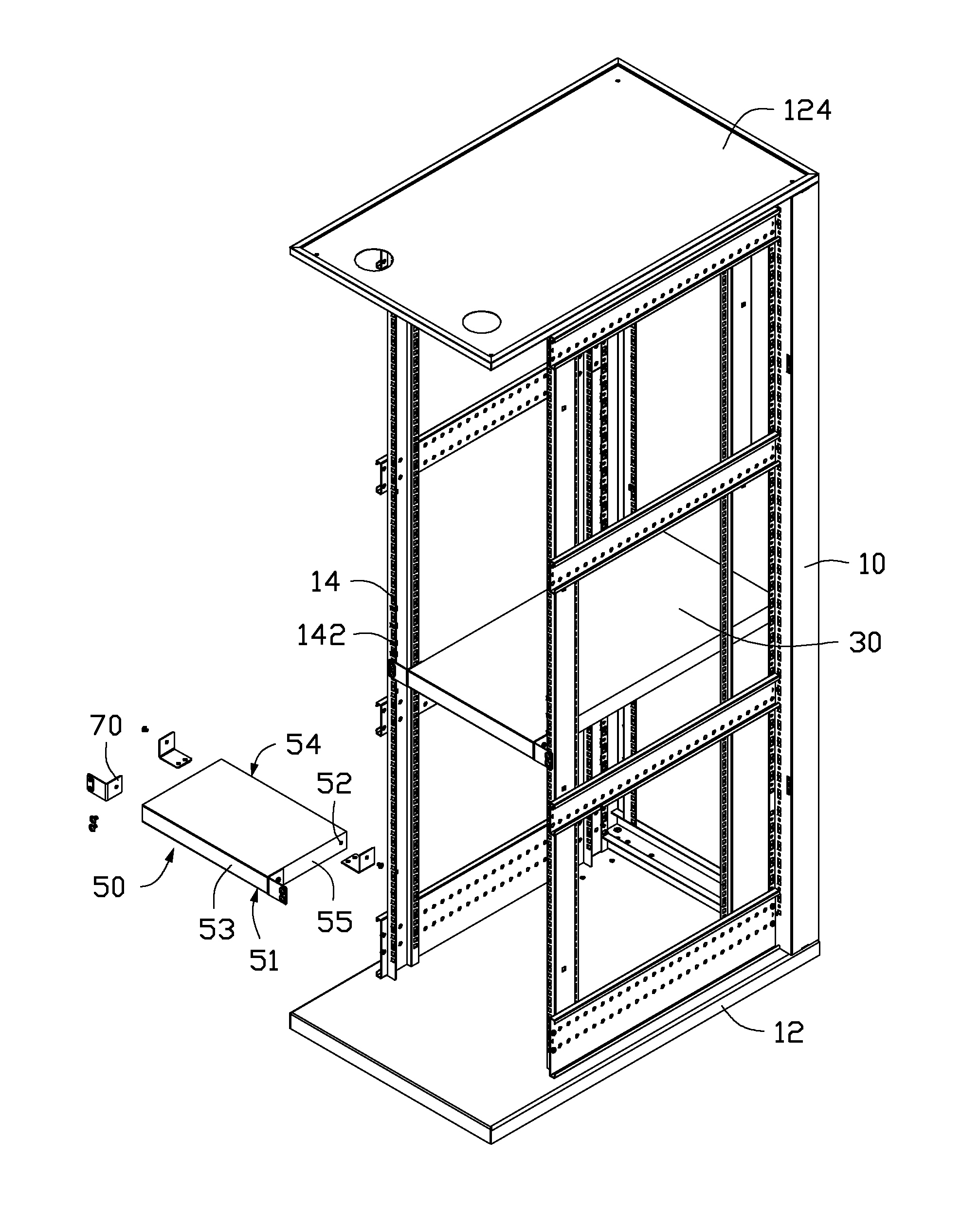
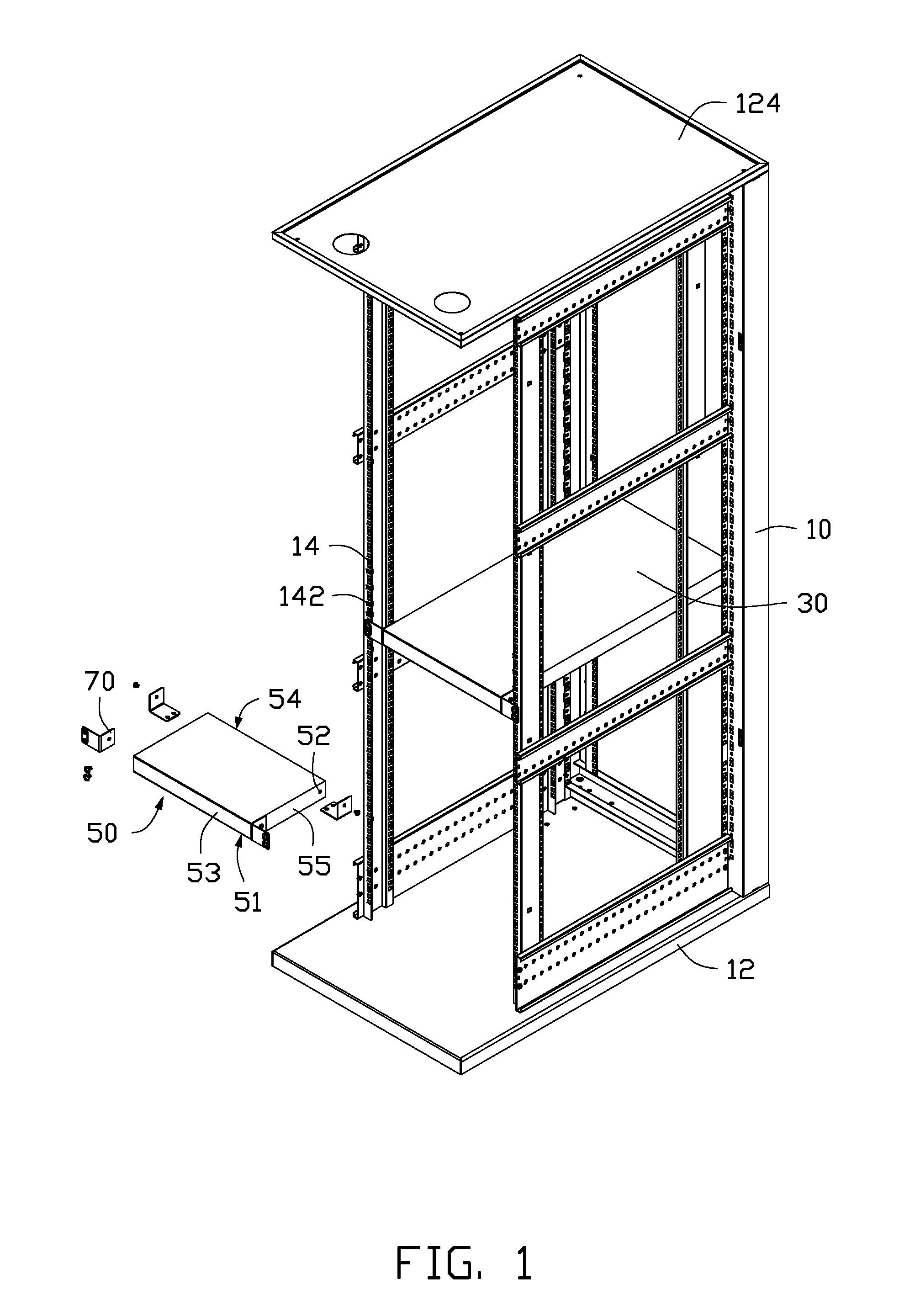
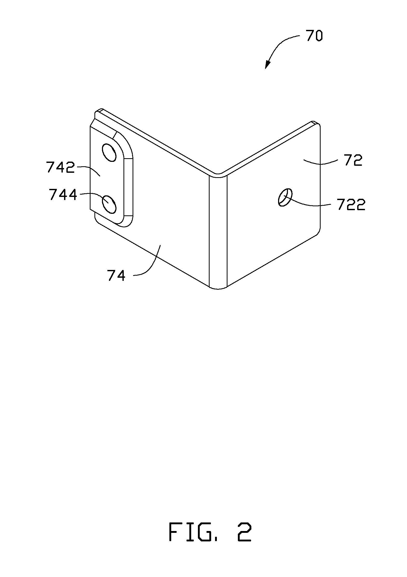
[0011]FIG. 1 and FIG. 2 show an exemplary embodiment of a server cabinet. The server cabinet includes a rack 10, a server 30, a switch 50, and four supporting members 70.

[0012]The rack 10 includes a rectangular base 12, four vertical columns 14 located at four corners of the base 12, and a top wall 124 supported on top ends of the columns 14. Each column 14 defines a plurality of positioning holes 142 arrayed along a lengthwise direction of the column 14. The server 30 is installed among the columns 14.

[0013]The switch 50 includes a bottom wall 51, a front wall 53 perpendicularly extending up from a front side of the bottom wall 51, a rear wall 54 perpendicularly extending up from a rear side of the bo...


PUM


Abstract

A server cabinet includes a rack, a server, a switch, and a first supporting member. The rack includes two columns located at a front end of the rack. The server is installed between the columns. The switch is installed in the rack above the server. Opposite ends of a front side of the switch are fastened to the columns of the rack. The first supporting member includes a connecting plate mounted to a rear side of the switch, and a supporting plate extending out from an end of the connecting plate and located below the switch. A raised portion protrudes down from the supporting plate. The raised portion is supported on the server.

Description

BACKGROUND[0001]1. Technical Field[0002]The present disclosure relates to a server cabinet.[0003]2. Description of Related Art[0004]In a server cabinet, a front end of a switch is generally fastened to a rack of the cabinet by screws. However, if the switch is long and heavy, a rear end of the switch may tilt and damage the bonding by screws between the front end of the switch unit and the cabinet.BRIEF DESCRIPTION OF THE DRAWINGS[0005]Many aspects of the present embodiments can be better understood with reference to the following drawings. The components in the drawings are not necessarily drawn to scale, the emphasis instead being placed upon clearly illustrating the principles of the present embodiments. Moreover, in the drawings, all the views are schematic, and like reference numerals designate corresponding parts throughout the several views.[0006]FIG. 1 is an exploded, isometric view of an exemplary embodiment of a server cabinet, wherein the server cabinet includes a plurali...

Claims


Application Information

Patent Timeline
Patent Type & Authority Applications(United States)
IPC IPC(8): H05K7/18
CPCH05K7/18H05K7/1488
Inventor SUN, ZHENG-HENG
Owner CLOUD NETWORK TECH SINGAPORE PTE LTD
Why Eureka
Try Eureka