Light-emitting device and control method of the same

a technology of light-emitting devices and control methods, which is applied in the direction of lighting apparatus, electroluminescent light sources, light sources, etc., can solve the problems of easy damage to other units, increased transfer voltage drop value, and malfunction of light-emitting units, so as to reduce the dc voltage

Active Publication Date: 2014-07-31
DELTA ELECTRONICS INC
View PDF0 Cites 3 Cited by
  • Summary
  • Abstract
  • Description
  • Claims
  • Application Information

AI Technical Summary

Benefits of technology

[0008]Therefore, an aspect of the present disclosure is to provide a light-emitting device, which includes: a light-emitting module, a plurality of current control units and a control module. The light-emitting module includes a plurality of light-emitting unit strings, each of the light-emitting unit strings includes a plurality of light-emitting units connected in series, and an end of each of the light-emitting unit strings receives a same DC voltage. Each of the current control units is connected in series to at least one of the light-emitting unit strings, so as to control a current of each of the light-emitting unit strings. The control module retrieves a voltage drop value across each of the current control units, so as to further determine whether the light-emitting units in each of the light-emitting unit strings malfunction; and when light-emitting units of a specific string among the light-emitting unit strings malfunction, and the number x of malfunctioned light-emitting units is larger than or equal to a malfunction threshold value p, the control module shorts the malfunctioned light-emitting units in the specific string and shorts (x−p+1) light-emitting units in each of the light-emitting unit strings other than the specific string and decrease the DC voltage received by each of the light-emitting unit strings, thereby achieving the effect of reducing the power consumption of the current control units.

Problems solved by technology

However, in the module mentioned above, the light-emitting units may malfunction.
Therefore, when the number of malfunctioned light-emitting units increases, the transferred voltage drop value rises and may easily damage other units.
However, when the entire string of light-emitting units is turned off because of a small amount of malfunctioned light-emitting units, the brightness of the light source is significantly reduced, which adversely affects the operating efficiency.
Therefore, it becomes an urgent problem to be solved in this technical field to design a new light-emitting device and method in which a flexible adjustment mechanism is provided to prevent the significant reduction of brightness of the light source when the light-emitting unit malfunctions.

Method used


Image

  • Light-emitting device and control method of the same
  • Light-emitting device and control method of the same
  • Light-emitting device and control method of the same

Examples


Embodiment Construction

[0027]Reference will now be made in detail to the present embodiments of the disclosure, examples of which are illustrated in the accompanying drawings. Wherever possible, the same reference numbers are used in the drawings and the description to refer to the same or like parts.

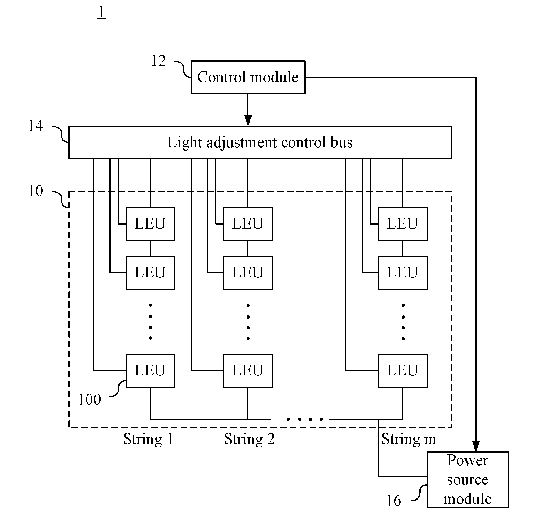
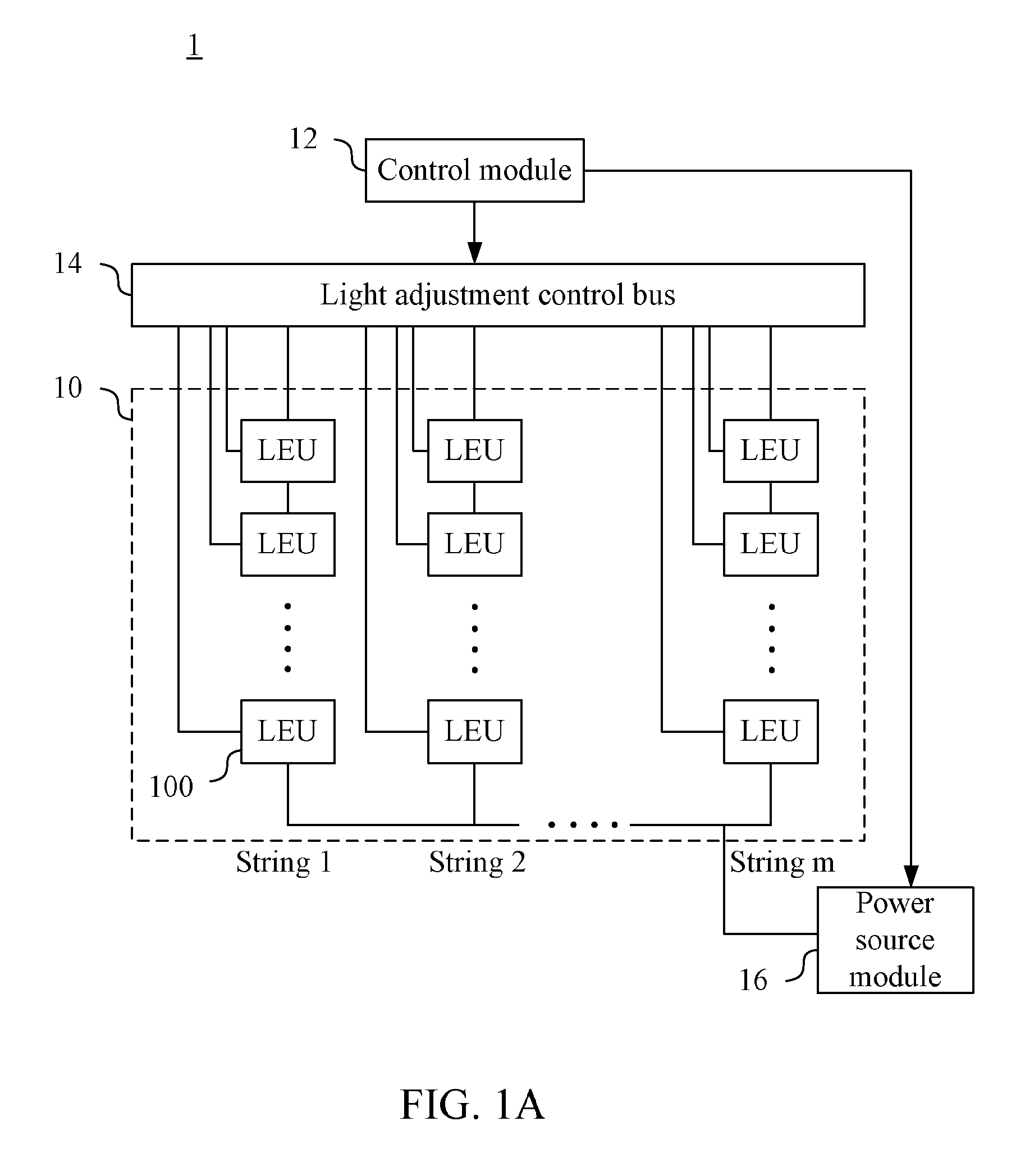
[0028]FIG. 1A is a circuit diagram of a light-emitting device 1 in an embodiment of the present disclosure. The light-emitting device 1 includes: a light-emitting module 10, a control module 12 and a light adjustment control bus 14.

[0029]The light-emitting module 10 includes a plurality of strings of light-emitting units, shown in FIG. 1A as String 1, String 2, . . . , and String m. Each of the light-emitting unit strings includes a plurality of light-emitting units 100 connected in series.

[0030]In the present embodiment, the light-emitting module 10 includes m light-emitting unit strings, and each of the light-emitting unit strings has n light-emitting units 100 (depicted as LEU in FIG. 1A) arranged in the f...


PUM


Abstract

A light-emitting device control method is provided. The light-emitting device control method comprises the steps outlined below. A light-emitting module of a light-emitting device having light-emitting unit string each having light-emitting units connected in series is operated. One end of each light-emitting unit strings receives a same DC voltage. A voltage drop value across each current control units connected in series to at least one of the light-emitting unit strings is retrieved to further determine whether the light-emitting unit of each of the light-emitting unit strings malfunctions. When x light-emitting units of a specific string malfunction and x is larger than or equal to a malfunction threshold value p, the x malfunctioned light-emitting units are shorted and (x−p+1) light-emitting units in each of the light-emitting unit strings other than the specific string are shorted. The DC voltage received by each of the light-emitting units is decreased.

Description

RELATED APPLICATIONS[0001]This application claims priority to Taiwan Application Serial Number 102103476, filed Jan. 30, 2013, which is herein incorporated by reference.BACKGROUND[0002]1. Technical Field[0003]The present disclosure relates to the light-emitting module control technology, and in particular, to a light-emitting device and control method thereof.[0004]2. Description of Related Art[0005]Solid state light-emitting units, such as a light-emitting diode (LED), that is used for the backlight source of the display panel or the light source used for illumination gradually become the mainstream technology. In a backlight source of a display panel, for example, light-emitting units are usually integrated into a module, so as to provide a uniform light source for the display panel, in which the module includes light-emitting units connected in series. However, in the module mentioned above, the light-emitting units may malfunction. When one of the light-emitting units connected ...

Claims


Application Information

Patent Timeline
Patent Type & Authority Applications(United States)
IPC IPC(8): H05B37/03H05B44/00
CPCH05B37/036H05B45/48H05B45/46H05B45/50H05B45/44
Inventor LIU, BAO-KIMHSIAO, TING-LUNG
Owner DELTA ELECTRONICS INC
Why Eureka
Try Eureka