
Direct-current transmission regulating method with multiple current transformers

A converter and inverter technology, applied in the direction of converting AC power input to DC power output, power transmission AC network, output power conversion device, etc., can solve the problems of instability, high cost of adjustment structure, and achieve cost more dynamic effects

Inactive Publication Date: 2008-09-24
SIEMENS AG
View PDF11 Cites 2 Cited by
  • Summary
  • Abstract
  • Description
  • Claims
  • Application Information

AI Technical Summary

Problems solved by technology

The disadvantage of this known method is that an adjustment layer on the upper level is required
But a hierarchical regulatory structure is expensive and can lead to undesired instability

Method used


Image

  • Direct-current transmission regulating method with multiple current transformers
  • Direct-current transmission regulating method with multiple current transformers

Examples


Embodiment Construction

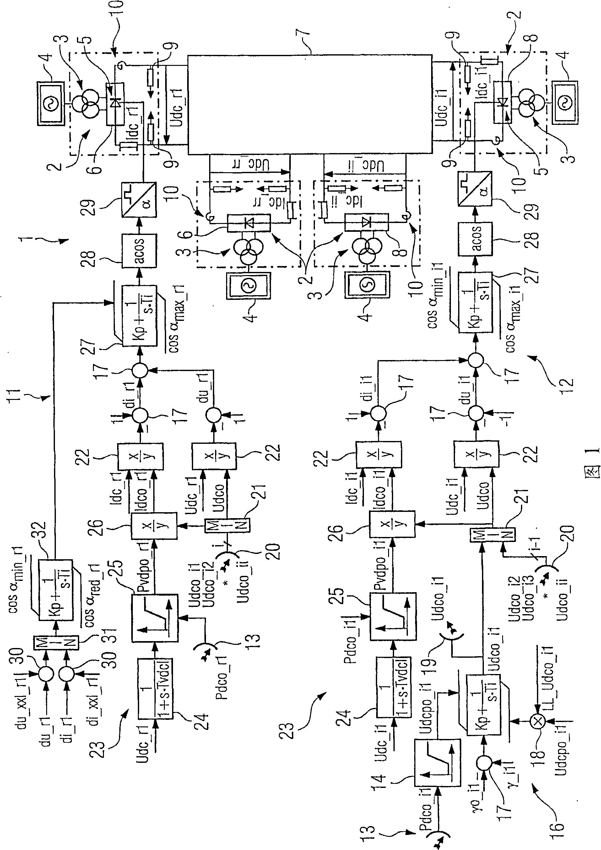
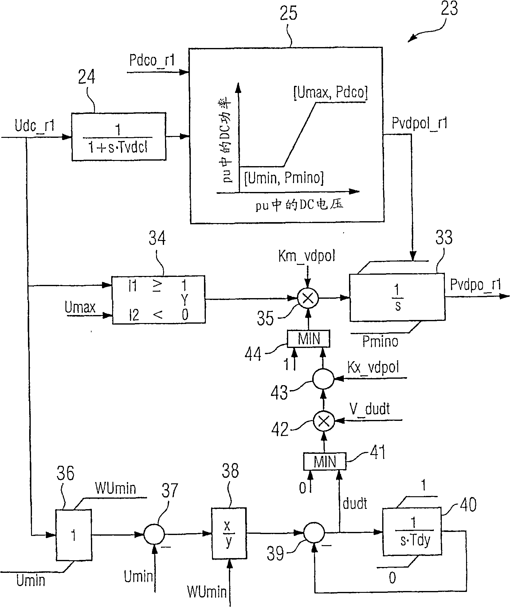
[0024] Figure 1 schematically illustrates an embodiment of the process of the present invention. A so-called multi-terminal HVDC transmission system 1 with several converters 2 (Multi-Terminal-Hochspannungsgleichstromübertragungs, MT- ) shows that the shown embodiment of the method according to the invention is used for regulation of the system. The MT- 1 includes a power transformer 3 for each converter 2, which is used for coupling the respective converter 2 to the AC grid 4. Each mains transformer 3 here has a primary winding electrically connected to the alternating current network 4 , which is inductively connected to two secondary windings of the mains transformer 3 . The secondary coils of the power transformer 3 provide different phase deviations to realize a so-called 12-pulse HVDC transmission system (12-Puls- -System)1. The 12-pulse HVDC transmission system is well known to those skilled in the art, so no detailed description is required here.

[0025] The s...


PUM


Abstract

The invention relates to a method for controlling at least three power converters (2), which can be controlled by a rectifier (6) or an inverter (8) and are connected together by a direct current network (7), in the region of power distribution and power transmission. The aim of the invention is to provide a method which has a simple structure and also works in a reliable manner. As a result, a measuring direct current voltage (Udc_l, ... Udc_rr; Udc_il ... Udc_ii) and a measuring direct current (Idc__rl, ... Idc_rr; Idc__il, ... Idc_ii) are measured on each power converter and respectively, transmitted to the respective rectifier control (11) and / or inverter control (12), and a rectifier desired direct power and / or inverter desired direct power (Pdco_rl, ... Pdco-rr,- Pdco_il, ... Pdco_ii) is determined for each power converter. The total of all desired direct powers (Pdco_rl, ...; Pdco_rr; Pdco-il, ... Pdco_ii) is equal to zero, and a desired direct voltage (¿˜dco_rl, ... Udco_rr; Udco__il, ... Udco_ii) is determined from each desired direct power, the smallest inverter desired direct voltage (Udco_il, ... Udco_ii) of all connected inverters (8) is fixed as minimal direct voltage (Udco) by means of a minimal direct voltage and the desired direct voltage, a desired direct current (Idco_rl; ... Idco_rr; Idco_il, ... Idco_ii) is formed from the minimal voltage (Udco) and the measuring direct voltage, a differential direct voltage (du_rl, ... du_rr, du_il, ... du_ii) is formed from the minimal voltage (Udco) and the differential direct current (di_rl; ... di_rr; di_il, ... di_ii) is formed from the desired direct current and the measuring direct current.

Description

technical field [0001] The invention relates to a method for regulating at least three converters in the field of energy distribution and transmission, which are adjustable as rectifiers or inverters and are connected to one another via a DC network. Background technique [0002] Such a method is known, for example, from DE 19544777 C1. The method described there is used to regulate a so-called HVDC transmission system, which consists of a plurality of converters, wherein the converters are operated optionally as rectifiers or inverters. In this case, the converters are connected to each other via a DC grid. Transformers are provided to couple the converters with respective corresponding energy distribution networks. When regulating the rectifier or inverter, the DC current and DC voltage of the individual converters are recorded as measured values. In addition, nominal value pairs in the form of nominal current values ​​and nominal voltage values ​​are determined for eac...

Claims


Application Information

Patent Timeline
Patent Type & Authority Applications(China)
IPC IPC(8): H02M7/757H02J3/36
CPCY02E60/60H02J3/36
Inventor 弗朗兹·卡利西克-梅尔
Owner SIEMENS AG
Learn More