Positive feedback latch amplitude limiting control circuit and method of passive radio frequency identification tag

A technology for identifying tags and passive radio frequency, applied in the field of radio frequency identification, can solve problems such as lack of communication distance, achieve the effect of no static power consumption, easy implementation, and reduced leakage current

Pending Publication Date: 2021-01-29
EXCELIO TECH SHENZHEN
View PDF5 Cites 1 Cited by
  • Summary
  • Abstract
  • Description
  • Claims
  • Application Information

AI Technical Summary

Problems solved by technology

In the application of long-distance response of passive RFID tags that this application focuses on, the leakage of nanoampere l

Method used


Image

  • Positive feedback latch amplitude limiting control circuit and method of passive radio frequency identification tag
  • Positive feedback latch amplitude limiting control circuit and method of passive radio frequency identification tag
  • Positive feedback latch amplitude limiting control circuit and method of passive radio frequency identification tag

Examples


Embodiment 1

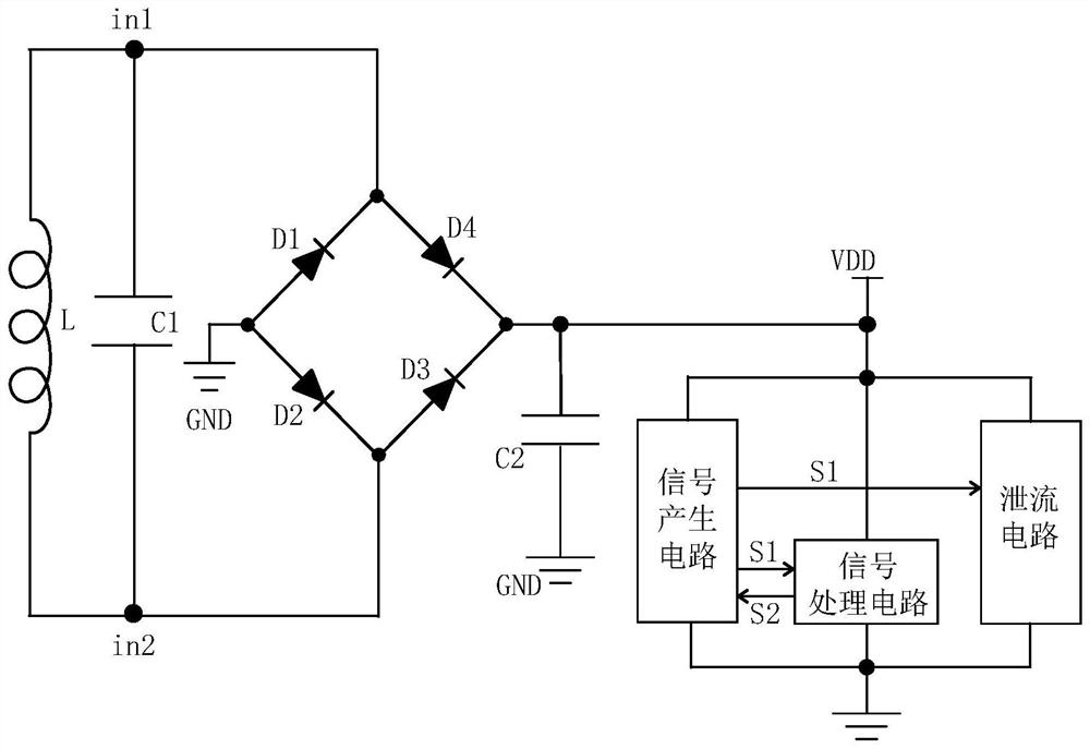
[0044] A positive feedback latch limiter control circuit of a passive radio frequency identification tag described in the present invention, such as figure 1 As shown, it includes a resonant circuit, a rectifier circuit and an energy storage capacitor C2, and the circuit also includes a signal generating circuit, a signal processing circuit and a discharge circuit,

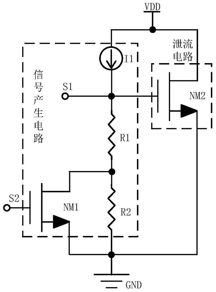
[0045] The signal generation circuit is connected between the output terminal of the rectification circuit and the ground, and is used to generate the first control signal S1 that changes with the change of the magnetic field strength coupled to the passive RFID tag coil, and input the first control signal S1 to the signal processing circuit and the leakage circuit, and receive the logic signal S2 returned by the signal processing circuit;

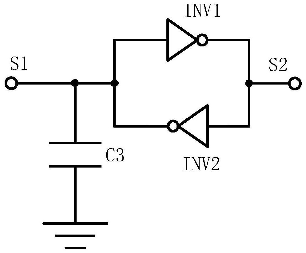
[0046] The signal processing circuit is connected between the output terminal of the rectifier circuit and the ground, and is used to receive the first control signal S1, and ...

Embodiment 2

[0060] Figure 5 It is a block diagram of the circuit structure of Embodiment 2 of the present invention. In this embodiment, the positive feedback latch limiter control circuit includes a resonant circuit, a rectifier circuit and an energy storage capacitor C2, and the circuit also includes a signal generating circuit. The first signal a processing circuit and a first bleeder circuit, and a second signal processing circuit, a second signal control circuit and a second bleeder circuit,

[0061] The signal generation circuit is connected between the output terminal of the rectification circuit and the ground, and is used to generate the first control signal S1 that changes with the change of the magnetic field strength coupled to the passive RFID tag coil, and input the first control signal S1 to the first signal processing circuit, the first discharge circuit, and the second signal processing circuit, and receive the logic signal S2 returned by the first signal processing circ...


PUM


Abstract

According to the positive feedback latch amplitude limiting control circuit and method of the passive radio frequency identification tag, dynamic rectification control can be carried out on the voltage between the first antenna end and the second antenna end, and when the voltage of the antenna end is too high, the signal generation circuit conducts the bleeder circuit, so that charges at the antenna end are output to the ground, and rectified direct-current voltage is reduced; when the voltage of the antenna terminal is within a limited voltage, the signal generation circuit enables the bleeder circuit to be in a cut-off state, and the rectification circuit rectifies all charges of the antenna terminal into a direct-current power supply for the load circuit to use, so that the current consumption is controlled to a certain extent. Moreover, the bleeder circuit is an MOS transistor of which the gate voltage is controlled by a latch, and a positive feedback latch mechanism in the latchenables a first control signal S1 to have very strong pull-down driving force when being pulled to a low level, so that the control gate of the bleeder circuit is thoroughly turned off, the electric leakage state of a sub-threshold region is avoided, The leakage current in the discharge path is effectively reduced, and the communication performance is improved.

Description

technical field [0001] The invention belongs to the technical field of radio frequency identification, and specifically refers to a positive feedback latch limiter control circuit applied to passive passive radio frequency identification tags, and a method for performing hierarchical limiter control by using the positive feedback latch limiter control circuit . Background technique [0002] The passive radio frequency identification (Radio Frequency Identification, RFID) tag does not have a battery itself, and it works by the electromagnetic energy sent by the card reader. Because of its simple structure, economical and practical, it has been widely used in logistics management, asset tracking and mobile medical fields. [0003] When a passive RFID tag works, it absorbs the electromagnetic energy sent by the reader from the surrounding environment. After the passive RFID tag absorbs energy, it rectifies a part of the energy into a DC power supply for the internal circuit o...

Claims


Application Information

Patent Timeline
IPC IPC(8): G06K19/07G06K19/073H02J50/20
CPCG06K19/0723G06K19/073G06K19/0708H02J50/20G06K19/0715G06K19/07773
Inventor 吴边王祥仁
Owner EXCELIO TECH SHENZHEN
Why Eureka
Try Eureka