Electric Power Converter

a technology of electric converters and power converters, applied in the field of electric converters, can solve the problems of reducing the capacitance of the capacitive region, affecting the operation of the whole converter, and most semiconducting elements remain open in a failure mode, so as to reduce the converter voltage rating, increase the availability of vsc, and reduce the effect of converter voltage rating

Inactive Publication Date: 2009-11-19
ABB (SCHWEIZ) AG
View PDF3 Cites 2 Cited by
  • Summary
  • Abstract
  • Description
  • Claims
  • Application Information

AI Technical Summary

Benefits of technology

[0009]Considering the voltage rating of the VSC, the DC voltage is the designing parameter. If all redundant semiconducting elements plus one active semiconducting element are broken, the DC voltage is decreased to allow the remaining components to stay within their voltage rating. The benefit is an increased availability of the VSC and converting forced outages to deferred or planned outages. However, the system impact is a reduction of the converter voltage rating. In a compensator for reactive power the performance in the capacitive region may be reduced depending on the VSC operating point. In the inductive region, the capability of reactive power absorption by the VSC is not reduced even after failure of all redundant semiconducting elements plus one or more active semiconducting element.

Problems solved by technology

However, most such semiconducting elements stay open in a failure mode.
If one of these semiconducting elements experiences a malfunction the whole converter trips and must be brought out of operation.
But when one of the active semiconducting elements assumes a short circuit failure mode the converter trips and must be taken out of operation.
This means that the plant will be out of operation until it has been repaired with a new set of semiconducting elements.

Method used


Image

  • Electric Power Converter
  • Electric Power Converter
  • Electric Power Converter

Examples


Embodiment Construction

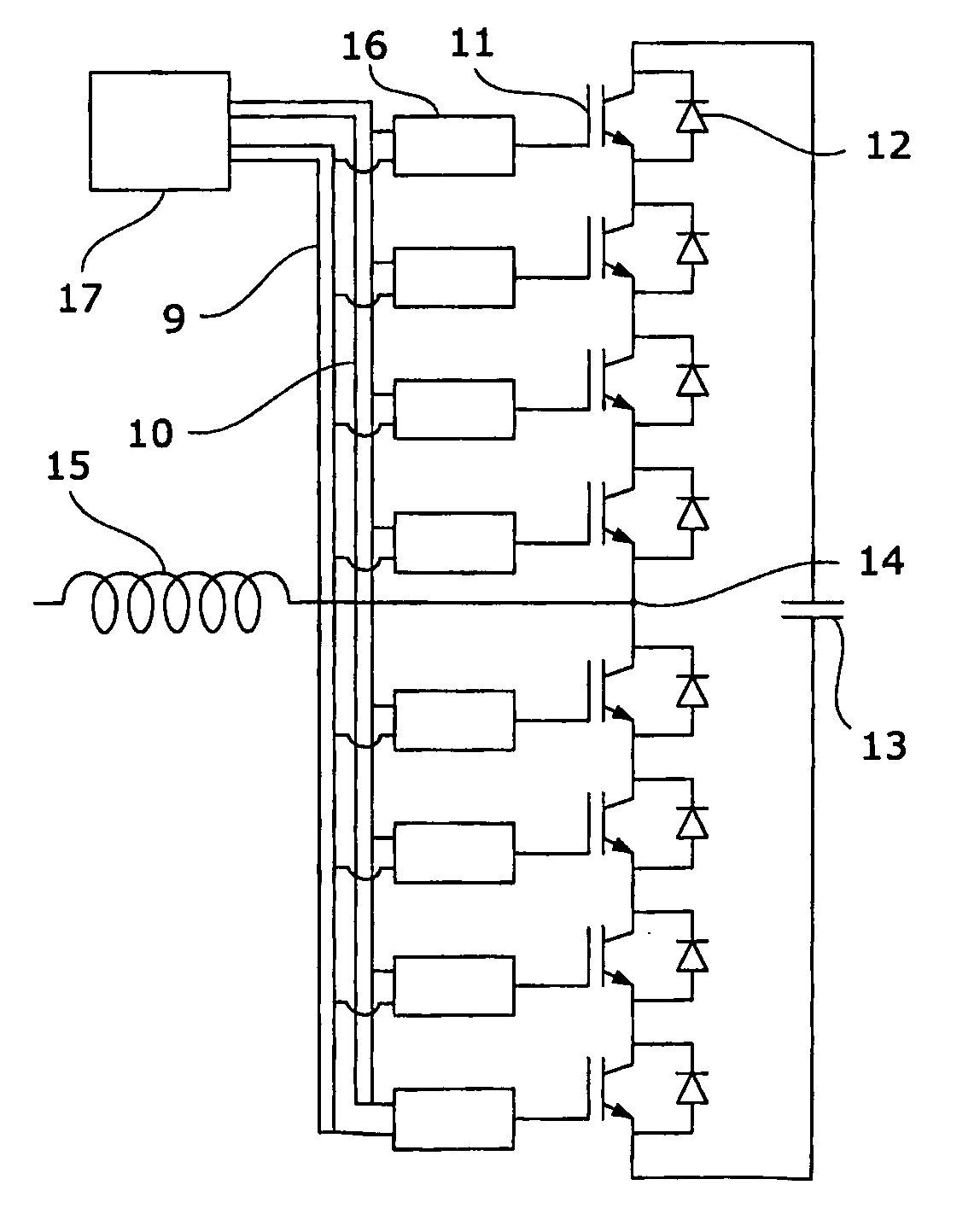
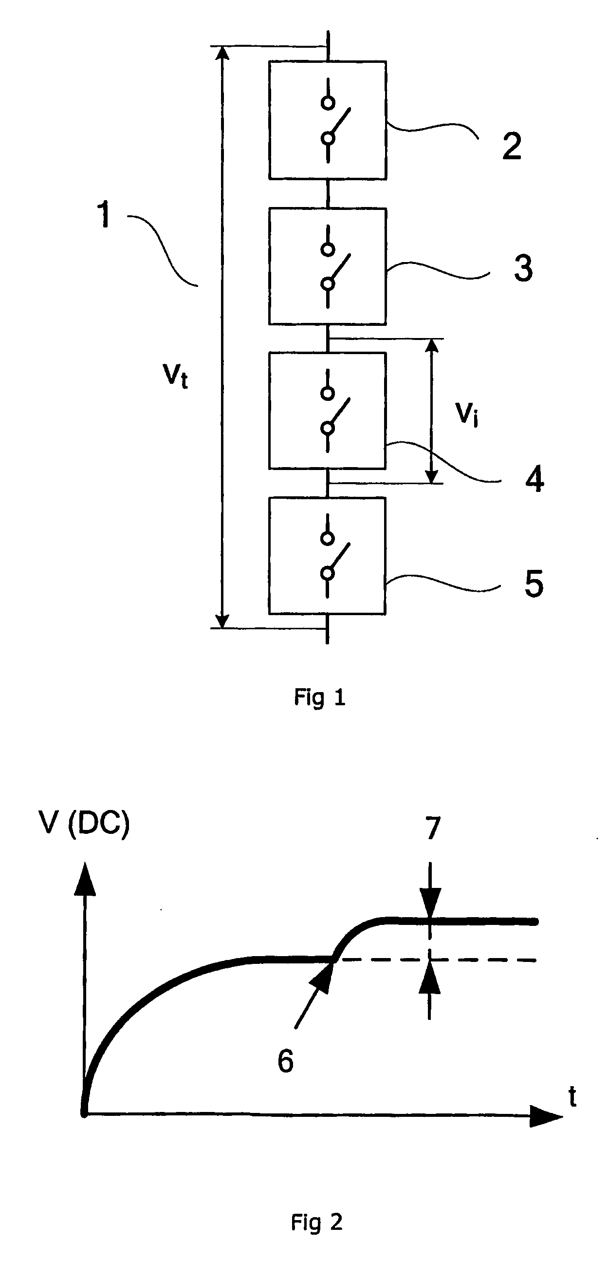
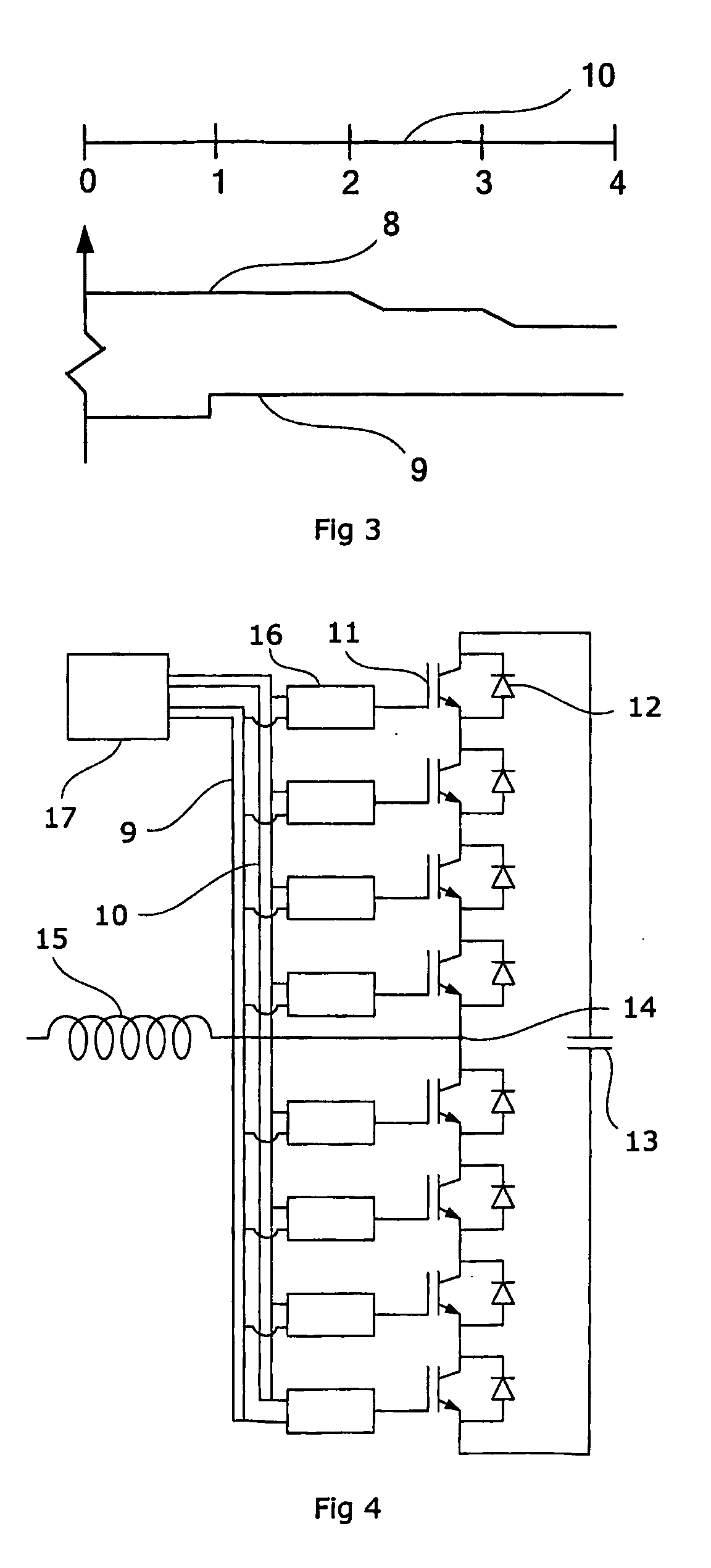
[0017]A string 1 of series connected switches 2, 3, 4, 5 is shown in FIG. 1. Each individual switch is denoted a switch symbol in order to show the necessity of the switch being capable at all times to assume a closed circuit or an open circuit as demanded from a control unit. Especially when series connected, the capability to assume a closed circuit is vital for the function of the converter. It is known to arrange the switches with semiconducting extinguishable elements. These semiconducting elements must thus comprise a short circuit failure mode.

[0018]When designing a string of series connected semiconducting elements care must be taken to redundancy. From design criteria the converter must have a defined operation capability. From long time experience it is known that semiconducting element has certain ability to break down. Hence a converter valve must contain as many semiconducting elements in series connection as the total dc voltage over the valve divided with the internal...


PUM


Abstract

A voltage source converter including a string of series connected active semiconducting elements. The converter includes in case of an active semiconducting element failure a calculation element configured to calculate an operation dc voltage including a sum of dc ratings of each remaining active semiconducting element in the string, and a regulator configured to regulate the converter to assume the operation dc voltage over the converter.

Description

TECHNICAL FIELD[0001]The present invention concerns an electric converter for high voltage applications comprising a plurality of series connected electric switches. Especially, the invention concerns a voltage source converter comprising extinguishable semiconducting means. In particular, the invention concerns a plurality of series connected semiconducting devices having a “short circuit failure mode”.[0002]By the expression short circuit failure should be understood that in case of failure of one of the series connected semiconducting elements the circuit is not open but kept closed. High voltage applications comprise distribution and transfer of electric power. Commonly the range for these applications is from 2 kV and upwards, and preferable from 5 kV and upwards.BACKGROUND OF THE INVENTION[0003]Common practice for designing a voltage source converter for high voltage applications involves series connected switches. Each switch has the function of opening and closing an electri...

Claims


Application Information

Patent Timeline
Patent Type & Authority Applications(United States)
IPC IPC(8): H02H9/04
CPCH02M1/088H02M7/538H02M1/32H01L25/117H03K17/0812
Inventor LARSSON, TOMASOLIVEIRA, MARCIO DEPETERSSON, KEHASLER, JEAN-PHILIPPE
Owner ABB (SCHWEIZ) AG
Why Eureka
Try Eureka