
Eureka
For R&D, Eureka makes reading and utilizing patents & technical documents easy.
Eureka AIR
Designed for self-driven R&D workflows. Generate viable solutions, solve complex R&D challenges, empower your innovation with AI.

Eureka Materials
Designed for material experts only. Revolutionize your material R&D, from search, analyze, to developing new materials.

TechResearch
Generate reliable direction feasibility study reports for your R&D in just a few steps.

TechSeek
Discover and master advanced knowledge NOW. Basics, ideas, possibilities, all at once.

TechMind
As an expert in R&D Theories, TechMind can generates customized viable solutions instantly.

TechRisk
Analyze your overall solution with one click, know your potential R&D risks in advance.

TechMonitor
Get weekly tech updates, stay abreast of the latest tech innovations and key insights.
Electric fluid pump
- Summary
- Abstract
- Description
- Claims
- Application Information
AI Technical Summary
Benefits of technology
Problems solved by technology
Method used
Image

Examples
Embodiment Construction
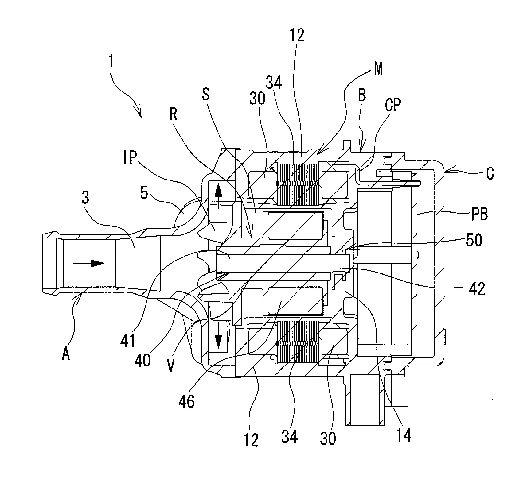
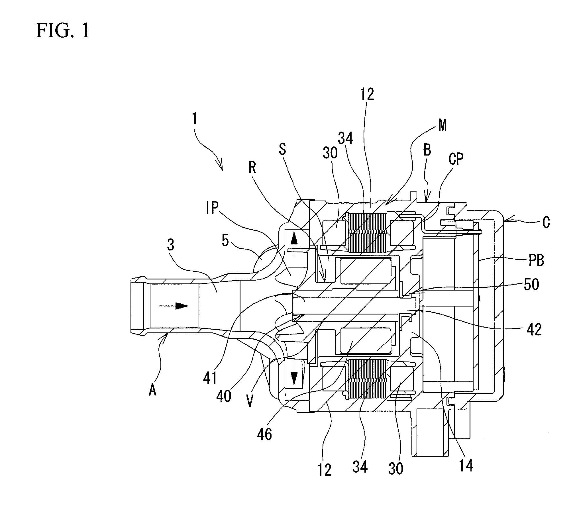
[0019]FIG. 1 is a sectional view of an electric fluid pump 1 according to the present embodiment. The electric fluid pump 1 is equipped with three cases A, B, and C. The case A is secured to the case B. The case B is secured to the case C. A motor M is arranged in the case B with parts buried therein. The motor M includes a rotor R, an iron core 30, and plural coils 34 wound around the iron core 30. A printed circuit board PB electrically connected to the coils 34 is arranged in the case C. The coils 34 and the printed circuit board PB are electrically connected via pins CP. The case A is formed with an inlet 3 for introducing the fluid and an outlet 5 for discharging the fluid. The case B is formed at its inside with a recess portion S in which the rotor R is arranged.
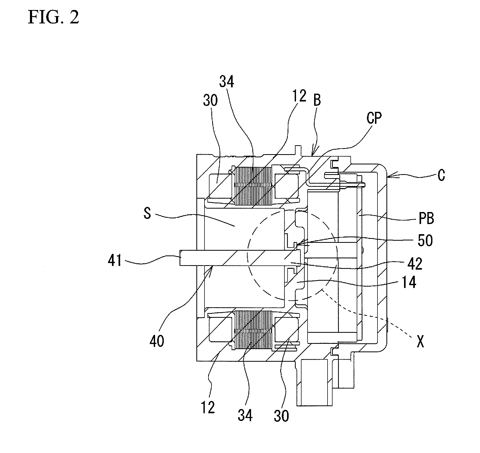
[0020]The case B includes a side wall portion 12 defining the recess portion S, and a bottom wall portion 14. The case B is made of a synthetic resin. The case B is insert-molded with the iron core 30, an axial member...
PUM
 Abstract
Description
Claims
Application Information
 - R&D Engineer
- R&D Manager
- IP Professional
- Industry Leading Data Capabilities
- Powerful AI technology
- Patent DNA Extraction
Browse by: Latest US Patents, China's latest patents, Technical Efficacy Thesaurus, Application Domain, Technology Topic, Popular Technical Reports.
© 2024 PatSnap. All rights reserved.Legal|Privacy policy|Modern Slavery Act Transparency Statement|Sitemap|About US| Contact US: help@patsnap.com