
Method and program editor for creating and processing a program for an industrial automation arrangement

a technology of program editor and program, applied in the direction of program control, process and machine control, instruments, etc., to achieve the effect of more fluid working/processing

Active Publication Date: 2014-08-28
SIEMENS AG
View PDF5 Cites 17 Cited by
  • Summary
  • Abstract
  • Description
  • Claims
  • Application Information

AI Technical Summary

Benefits of technology

The patent describes a method for a program editor of an industrial automation arrangement that allows for easy selection and replacement of program objects. The method includes presenting program objects as characters strings and using drag-and-drop technique to insert them into the program. The target position is then examined to determine if it contains a compatible program object and, if not, the selected program object is inserted into the text. This method makes it easier to work with the program editor and reduces the need for separate steps of replacing program objects. Additionally, the current operating mode of the program editor is considered and only those target program elements of the same or compatible object type can be replaced. This is useful when adopting programs from older programs or templates. The method also allows for larger capture range, resulting in more fluid working / processing.

Problems solved by technology

However, disadvantages related to the conventional dragging and dropping of program objects include that, on one hand, the target position must be very accurately indicated (e.g., between two letters, numbers or other characters) using the manipulation means (e.g., mouse pointer) and, on the other hand, if the program object manipulated in this manner (e.g., being dragged to be dropped) is intended to replace another program object, this other program object must be either previously deleted, or at least pre-marked.

Method used


Image

  • Method and program editor for creating and processing a program for an industrial automation arrangement
  • Method and program editor for creating and processing a program for an industrial automation arrangement
  • Method and program editor for creating and processing a program for an industrial automation arrangement

Examples


Embodiment Construction

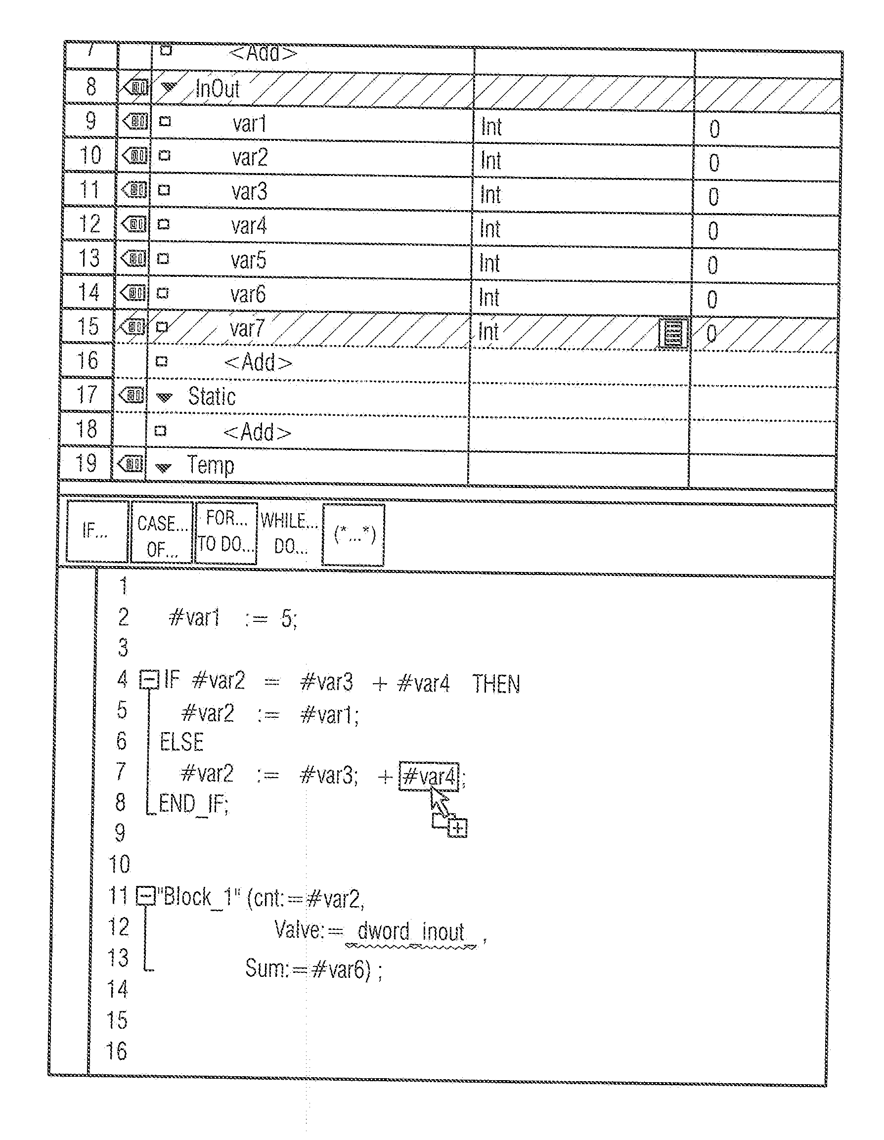
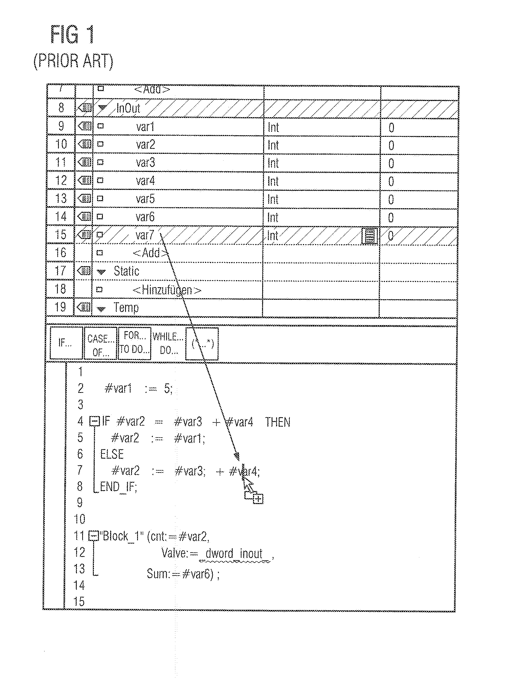
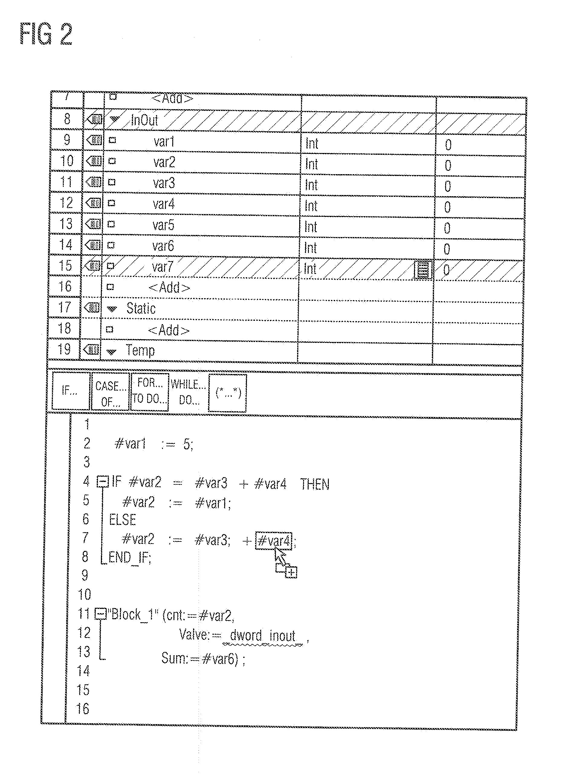
[0019]FIG. 1 illustrates a part of a user interface of a conventional program editor in the prior art. In this case, a list of variables containing variables var1, . . . , var7 of the “integer” type can be seen in the upper half of FIG. 1, in which case one of the variables is intended to be inserted into a section of a program (e.g., automation program) illustrated in the lower half of FIG. 1. This operation is illustrated using an arrow which symbolizes a known drag-and-drop operating procedure. The same starting configuration, i.e., the same list of variables as a “library” in the upper half of the respective figure and the same piece of program code in the lower half of the respective figure, applies to FIGS. 2-6 described below.

[0020]As mentioned, FIG. 1 illustrates the prior art, which can be seen from the fact that the selected character string “var7” is dragged into the text of the program using the operating procedure, to be precise specifically in the middle of the charact...


PUM


Abstract

A method for creating and processing a program includes selecting a new program object of an object type. The new program object is presented as a character string. The program is presented as text and a program object is presented as a character string when the program object is inserted into the program using drag-and-drop. The method also includes moving the selected program object to a target position in the program text. The method further includes examining the target position to determine whether a program object of the same or a compatible object type is present at the target position. If such a target program object is present at the target position, the method also includes replacing the target program object with the selected program object. Otherwise, the method includes inserting the character string representing the selected program object into the text of the program at the target position.

Description

CROSS-REFERENCE TO RELATED APPLICATIONS[0001]This application claims priority to European Patent Application No. EP 13157024, filed on Feb. 27, 2013, which is hereby incorporated in its entirety by reference.FIELD OF THE INVENTION[0002]The invention relates to a method for a graphical user interface of a program editor of an industrial automation arrangement and a program editor for creating and processing a program presented as text for an industrial automation arrangement.DESCRIPTION OF THE RELATED ART[0003]Programs for industrial automation arrangement (e.g., Programmable Logic Controller, or PLC) are still often created and processed as a text file. Such text-based programs still use program editors with graphical user interface and functionality that substantially correspond to the conventional word processing programs (also known as “word processors”).[0004]For example, users of the conventional program editors use known manipulation means (e.g., mouse, track-pad) in addition ...

Claims


Application Information

Patent Timeline
Patent Type & Authority Applications(United States)
IPC IPC(8): G06F9/44G06F3/0486
CPCG06F8/34G06F3/0486G05B19/056G06F8/33G05B2219/13144G05B2219/23291
Inventor PETZOLDT, JOERGSCHROEDER, CHRISTIAN
Owner SIEMENS AG
Learn More