Striking trainer

a trainer and trainer technology, applied in the field of striking trainers, can solve the problem of not providing multiple simulating modes for the exerciser to train himsel

Inactive Publication Date: 2014-10-09
CHEN TINA
View PDF4 Cites 33 Cited by
  • Summary
  • Abstract
  • Description
  • Claims
  • Application Information

AI Technical Summary

Benefits of technology

[0007]An object of the present invention is to provide a striking trainer, in whi...

Problems solved by technology

However, the conventional striking apparatus could only provide a swing range adjusting function, but the exerciser could not adjust a pivoting range bet...

Method used


Image

  • Striking trainer
  • Striking trainer
  • Striking trainer

Examples


Embodiment Construction

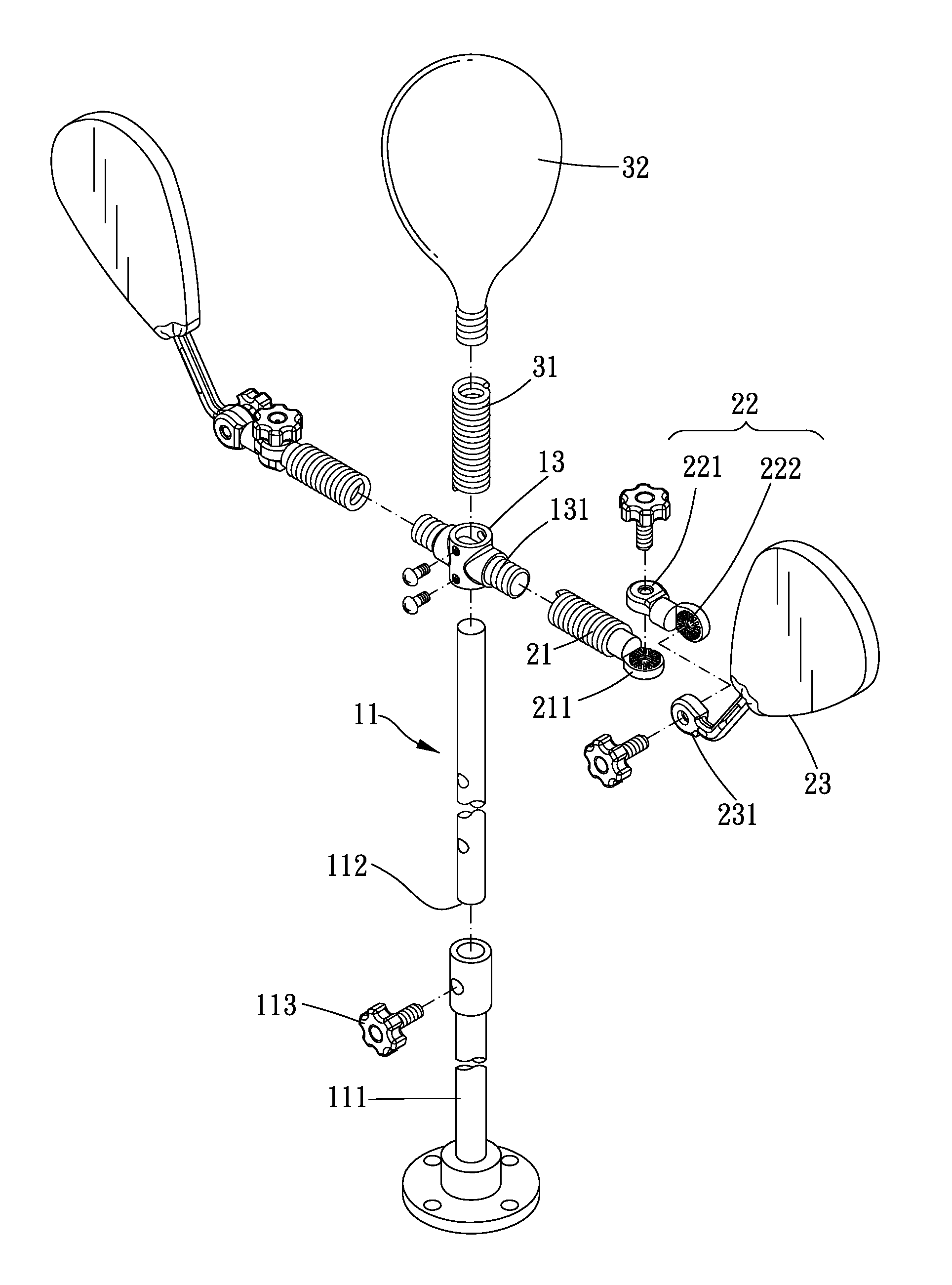
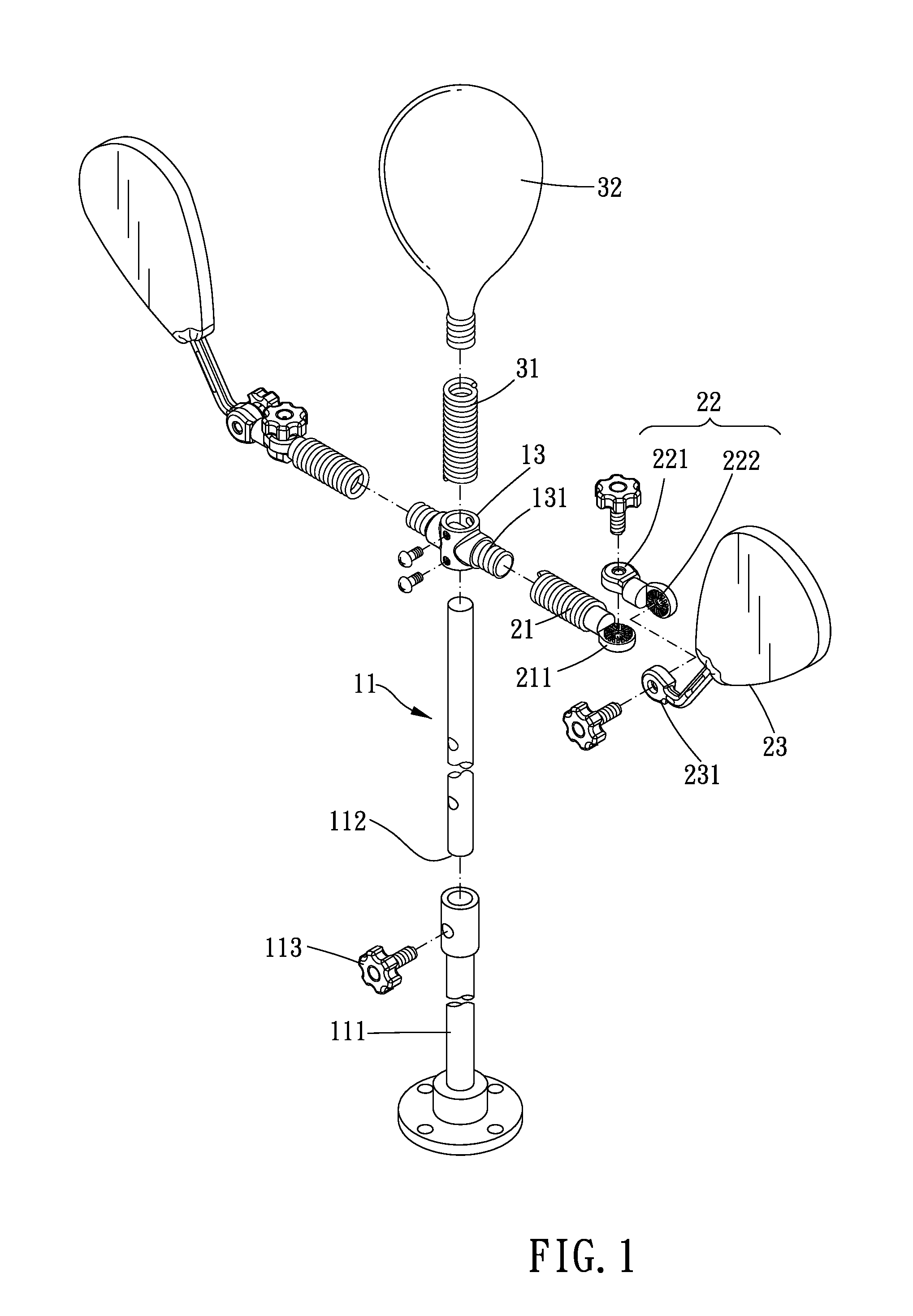
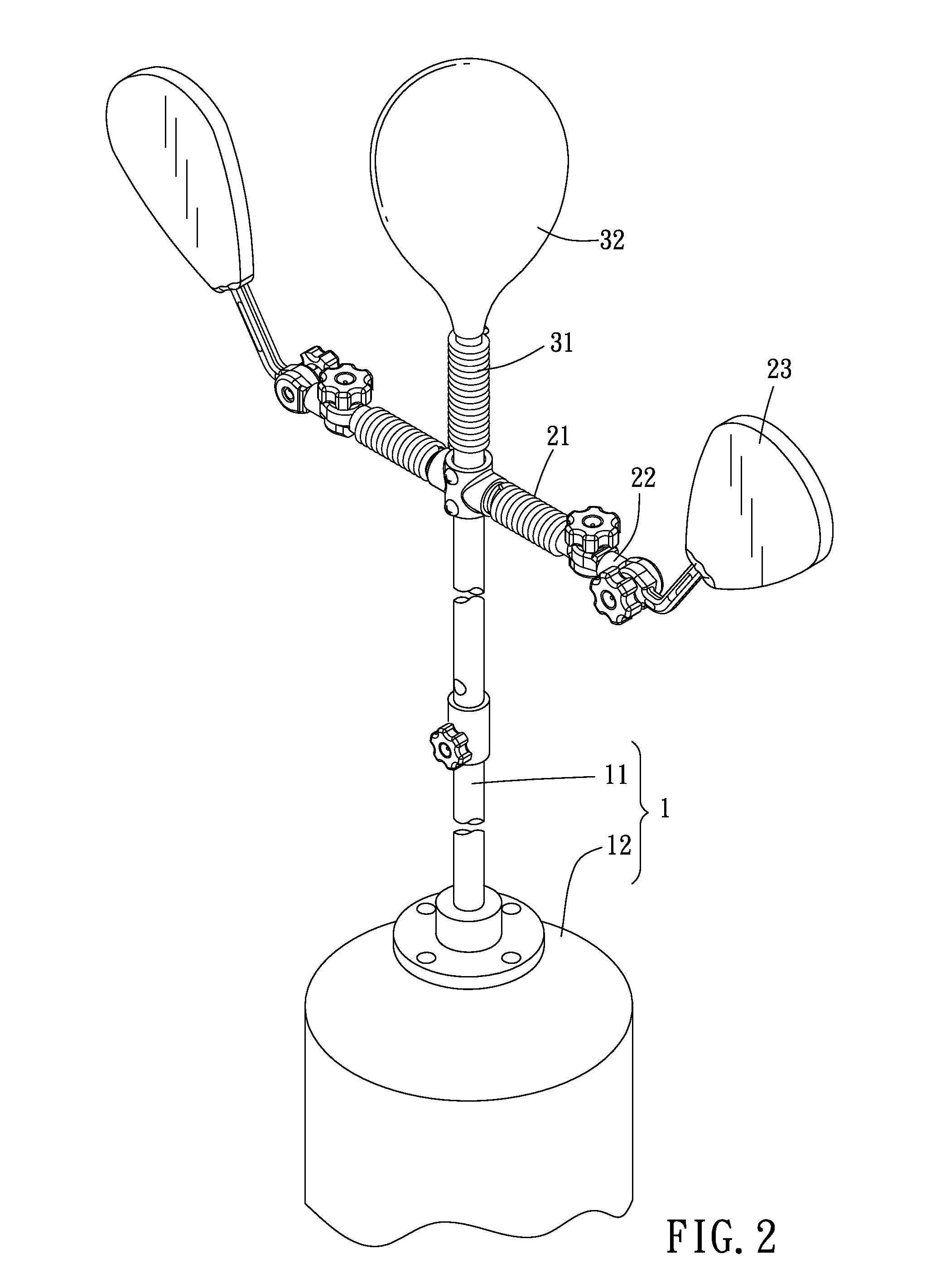
[0014]FIGS. 1-2 show a striking trainer according to a preferred embodiment of the present invention. The trainer includes a body 1 and at least one first striking assembly. The body 1 further comprises a rod member 11, a base 12 and a sleeve member 13. One end of the rod member 11 is connected to the base 12. The rod member 11 is sleeved by the sleeve member 13. A datum is perpendicular to a longitudinal direction of the body 1. Clearly, the longitudinal direction of the body 1 is equal to an extending direction of the rod member 11 and the datum is the ground level. The rod member 11 is telescopic and comprises a first portion 111, a second portion 112 sleeved by the first portion 111, and a fastener 113. The first portion 111 is connected to the base 12, and the second portion 112 is sleeved by the first portion 111. The first portion 111 has at least one first through hole, and the second portion 112 has a plurality of second through holes. The second through holes are axially a...


PUM


Abstract

A striking trainer is provided. The trainer includes a body and at least one first striking assembly. The first striking assembly further comprises an arm, a pivoting structure and a striking portion. The arm is assembled to the body. The pivoting structure has a first pivoting portion and a second pivoting portion. The arm has the first pivoting portion pivotally connected thereto and defines a first pivoting shaft thereon, so that the first pivoting portion is rotatable relative to the arm via the first pivoting shaft. The striking portion is pivotally connected to the second pivoting portion. A second pivoting shaft is defined on the second pivoting portion, so that the striking portion is rotatable relative to the second pivoting portion via the second pivoting shaft. Thus, the trainer provides a widely angle and range adjusting function from two different directions.

Description

BACKGROUND OF THE INVENTION[0001]1. Field of the Invention[0002]The present invention relates to a striking trainer.[0003]2. Description of the Prior Art[0004]A conventional striking apparatus comprises a rod connected to a base. A top end of the rod has a striking member assembled thereon, so that an exerciser could strike the striking member for training. Two elastic tubes are respectively assembled at two ends of the rod. One elastic tube is connected between the striking member and the rod, and the other elastic tube is connected between the base and the rod. The rod comprises two sliding members. Each sliding member could slide into the corresponding elastic tube so as to limit a swing range between the rod and the striking member. Under above arrangement, the exerciser could adjust a sliding distance between the elastic tube and the sliding member for adjusting the swing range between the striking member and the rod.[0005]However, the conventional striking apparatus could only...

Claims


Application Information

Patent Timeline
IPC IPC(8): A63B69/20
CPCA63B69/203A63B2225/09A63B2225/093A63B2244/10A63B69/224
Inventor CHEN, TINA
Owner CHEN TINA
Why Eureka
Try Eureka