Blind rivet with a plastic rivet body

a technology of blind rivets and plastic rivets, applied in the field of blind rivets, can solve the problems of door frame damage, module support damage, extra effort in removal from the latter, etc., and achieve the effect of facilitating the entry of the guide section, corresponding effect on setting force, and small siz

Active Publication Date: 2014-10-23
NEWFREY
View PDF48 Cites 2 Cited by
  • Summary
  • Abstract
  • Description
  • Claims
  • Application Information

AI Technical Summary

Benefits of technology

[0013]The invention has the advantage that the rivet body is guided on the rivet mandrel during the riveting process, and thus cannot slip laterally. The sections of the rivet body that rest upon one another during formation of the roll fold are held in a mutually centered position by the rivet mandrel and are thus forced to form a uniform and symmetrical annular bead.
[0014]Preferably, the guide element has a plurality of radially inward directed projections, which are arranged at a uniform spacing from one another in the circumferential direction. The projections can be embodied as longitudinal ribs that extend in the direction of the longitudinal c

Problems solved by technology

However, in cases in which repair of the joined parts is necessary or when a blind rivet has been set incorrectly, it is necessary to remove a blind rivet.
Thus it is not uncommon for the door frame and also the module support to be damaged during the drilling-out process.
The drilling chips and removed parts of the rivet fall to the ground or even into the blind area of the door, and can only be removed from the latter with extra effort.
However, it is disadvantageous here that the holding forces of the blind rivet are very limited, and, like the release forces, are strongly

Method used


Image

  • Blind rivet with a plastic rivet body
  • Blind rivet with a plastic rivet body
  • Blind rivet with a plastic rivet body

Examples


Embodiment Construction

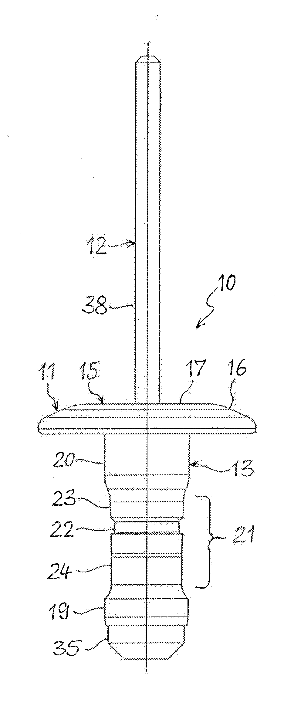
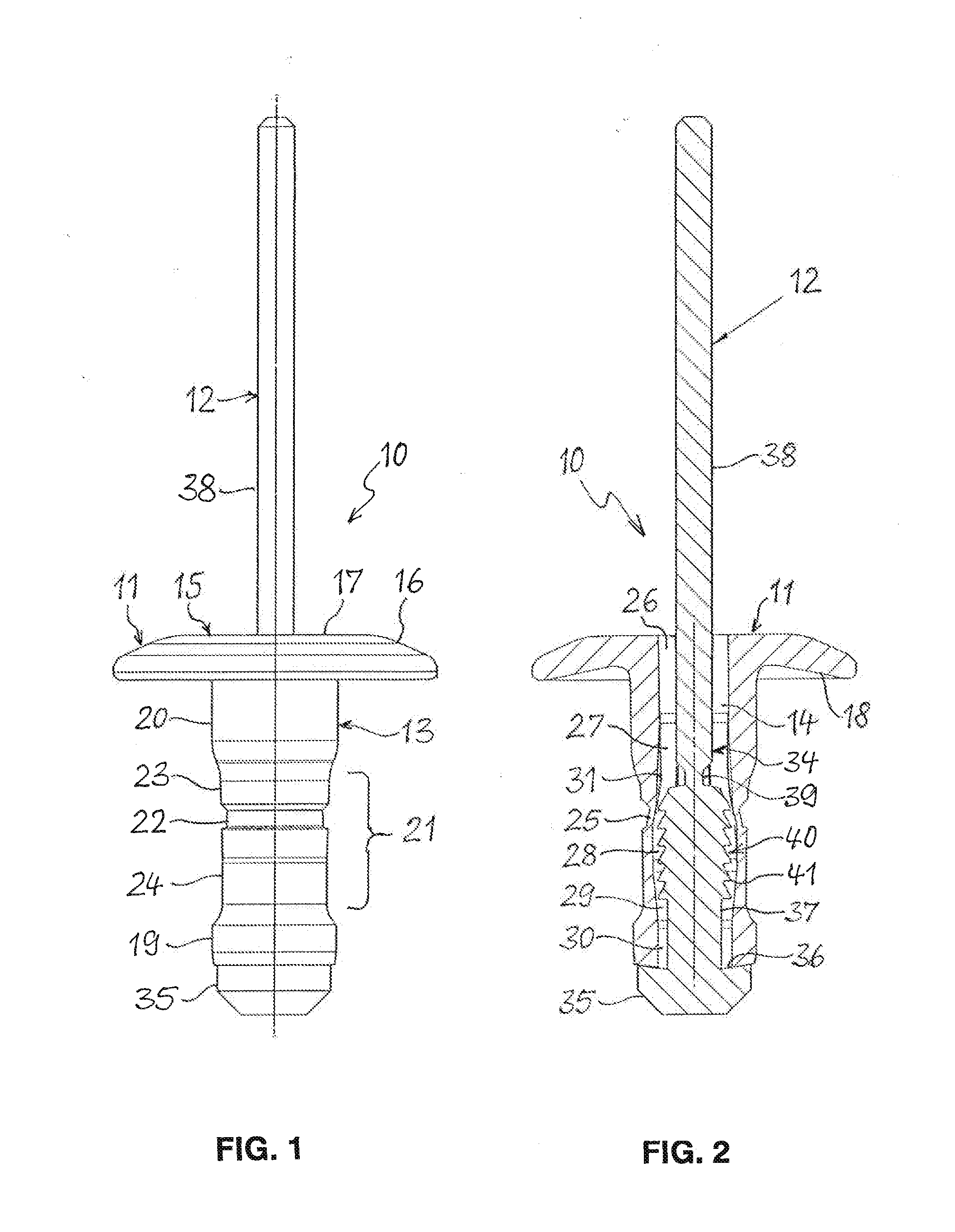
[0026]The blind rivet 10 shown in FIGS. 1 and 2 consists of a rivet body 11 and a mandrel 12. The rivet body 11 is made of plastic and has an elongated shank 13 with a through-bore 14, in which the mandrel 12 is located. One end of the shank 13 forms a head 15, which takes the form of a disk-shaped flange 16 and is intended to contact an accessible side of a workpiece. On the side facing away from the shank 13, the head 15 has a flat support surface 17 for supporting the forward end of a rivet setting tool. The flange 16 radially overhanging the shank 13 is domed in the manner of a spring washer, and has a concave contact surface 18 on the side facing the shank 13. As a result, the flange 16 can yield elastically when the head 15 of the blind rivet 10 is pressed against a workpiece.

[0027]The end of the shank 13 opposite the head 15 constitutes a foot end 19; with said foot end forward, the shank 13 is passed through the mounting openings of workpieces to be joined to one another. Th...


PUM


Abstract

A blind rivet having a hollow rivet body made of plastic, an elongated shank with a bore, a head at one end of the shank and a foot end on the opposite end of the shank, and having, in the bore, a mandrel that has a mandrel shank with a drawing end and a mandrel head that acts on the foot end, the shank has a first region located between the head and the foot end, and has a second region with reduced cross-section and reduced wall thickness as compared to the first region. The regions arranged such that, as a result of a process in which the head is pressed against one side of a workpiece and the foot end is simultaneously drawn toward the other side of the workpiece with the aid of the mandrel, the wall of the shank forms a roll fold with an annular bead.

Description

CROSS-REFERENCE TO RELATED APPLICATIONS[0001]This application is a continuation of PCT / EP2012 / 066474, filed Aug. 24, 2012 which claims priority from German Patent Application No. DE 10 2011 053 035.5, filed Aug. 26, 2011, the disclosure of which is incorporated herein by reference in its entirety.FIELD OF THE INVENTION[0002]The invention concerns a blind rivet having a hollow rivet body made of plastic, which has an elongated shank that extends coaxially to a longitudinal center axis of the blind rivet and has a bore, having a head extending radially at one end of the shank for contact with an accessible side of a workpiece, and having, at the opposite end, a foot end that is passed through an opening in the workpiece, and having, located in the bore of the rivet body, a mandrel that has a mandrel shank with a drawing end projecting out of the head of the rivet body and with a mandrel head that stands in operative connection with the foot end of the rivet body in order to transmit a...

Claims


Application Information

Patent Timeline
IPC IPC(8): F16B19/10
CPCF16B19/1036F16B19/1054F16B5/04F16B19/1045
Inventor SALTENBERGER, REIMAR
Owner NEWFREY
Why Eureka
Try Eureka