
Automatic digging and loading system for a work machine

a work machine and automatic technology, applied in the field of digging and loading systems, can solve the problems of operator fatigue, operator less efficiency, repetitive work cycle, etc., and achieve the effect of facilitating the movement of work implements and facilitating the entry of work implements

Active Publication Date: 2006-11-02
CATERPILLAR INC
View PDF52 Cites 68 Cited by
  • Summary
  • Abstract
  • Description
  • Claims
  • Application Information

AI Technical Summary

Benefits of technology

[0007] In another exemplary aspect, a method of controlling an automatic bucket control system for loading a work implement of a work machine with material from a pile is disclosed. The method may include monitoring a lift actuator and communicating a lift signal. The method may also include monitoring a tilt actuator and communicating a tilt signal. A speed signal indicative of a speed of the work machine may be communicated, and a signal may be generated to control a rim-pull based on at least one of a lift velocity of the lift actuator, a tilt velocity of the tilt actuator, and a work machine velocity to facilitate movement of the work implement through the pile.
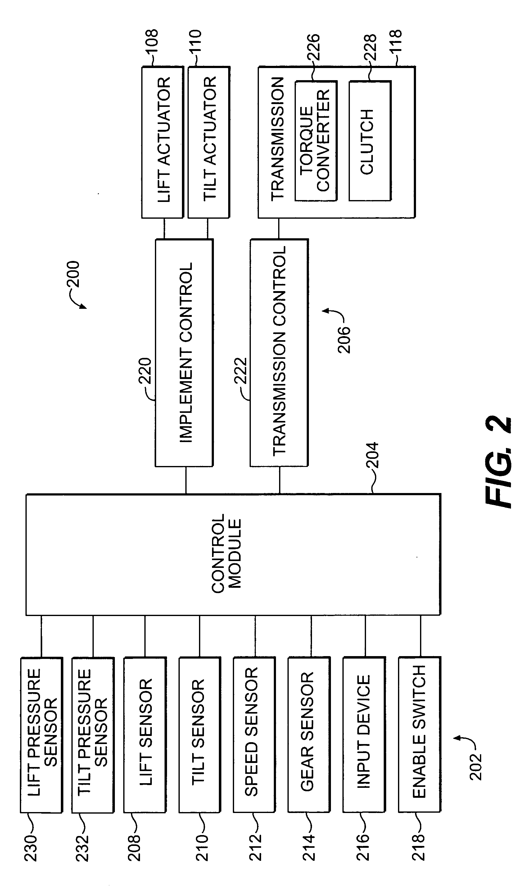
[0008] In yet another exemplary aspect, an automatic loading control system for loading a work implement of a work machine may include a lift sensor configured to monitor a lift actuator and communicate a lift signal. The loading control system may also include a tilt sensor configured to monitor a tilt actuator and communicate a tilt signal. A speed sensor may be configured to communicate a speed signal indicative of a speed of the work machine. A control module may be configured to receive the lift signal, the tilt signal, and the speed signal and generate a control signal to repetitively increase and decrease at least one of a lift velocity and a tilt velocity of the work implement to facilitate entry of the work implement into a pile of material while loading the work implement.

Problems solved by technology

Often, the repetitious work cycle can become tedious to an operator and the operator may become fatigued.
As the fatigue sets in, the operator may work less efficiently, thereby adversely impacting the efficiency of the work machine.
While these pressure and position measurements may be useful when loading an aggregate, such as gravel or sand that is loosely piled, such systems are less useful when digging hard materials.
For example, while the system disclosed in the publication provides for adjustment of lift and tilt commands based upon variations in a monitored ground speed, it may not provide for adjustment of speed based on velocities of the lift and tilt actuators.
Further, such a system may still require tuning and adjustment when loading piles of materials having differing densities and materials.

Method used


Image

  • Automatic digging and loading system for a work machine
  • Automatic digging and loading system for a work machine
  • Automatic digging and loading system for a work machine

Examples


Embodiment Construction

[0016] Reference will now be made in detail to exemplary embodiments that are illustrated in the accompanying drawings. Wherever possible, the same reference numbers will be used throughout the drawings to refer to the same or like parts. While specific configurations and arrangements are discussed, it should be understood that this is done for illustrative purposes only.

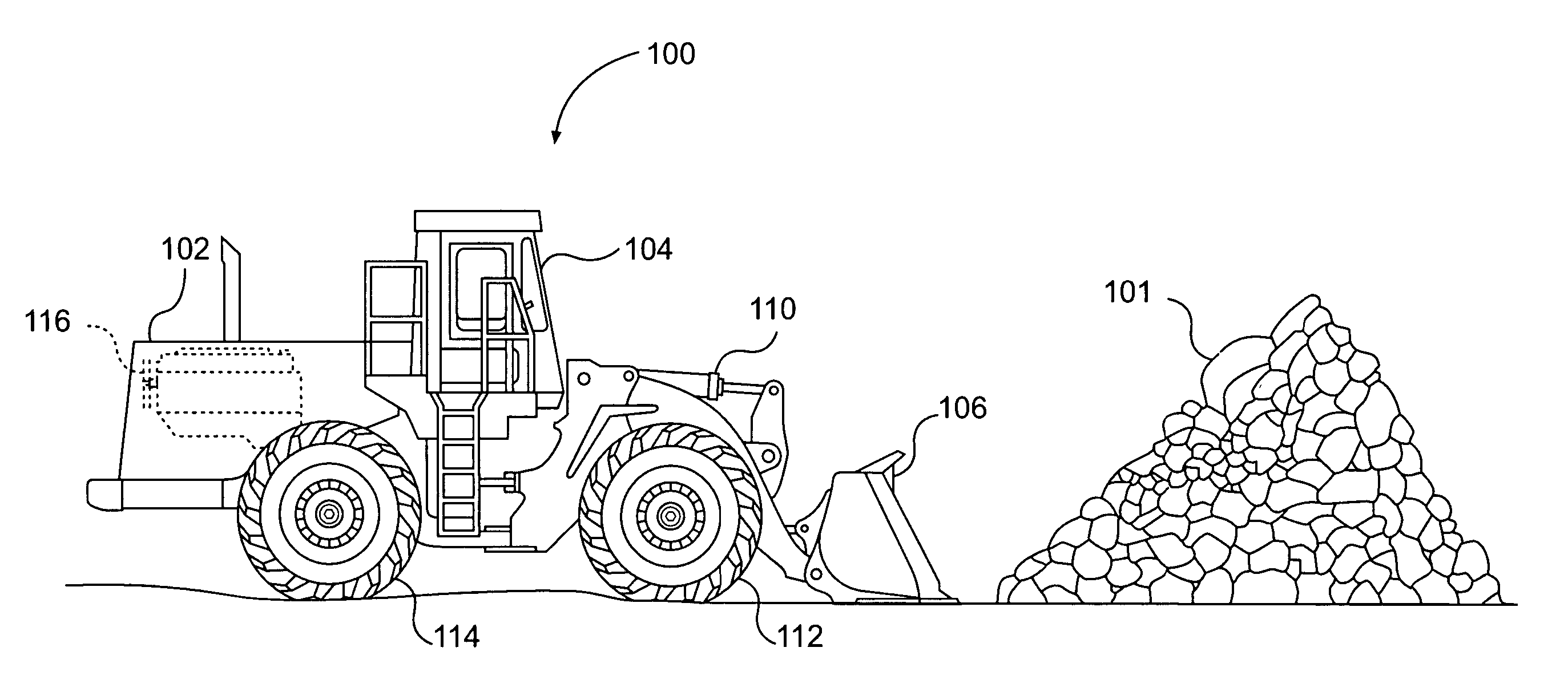
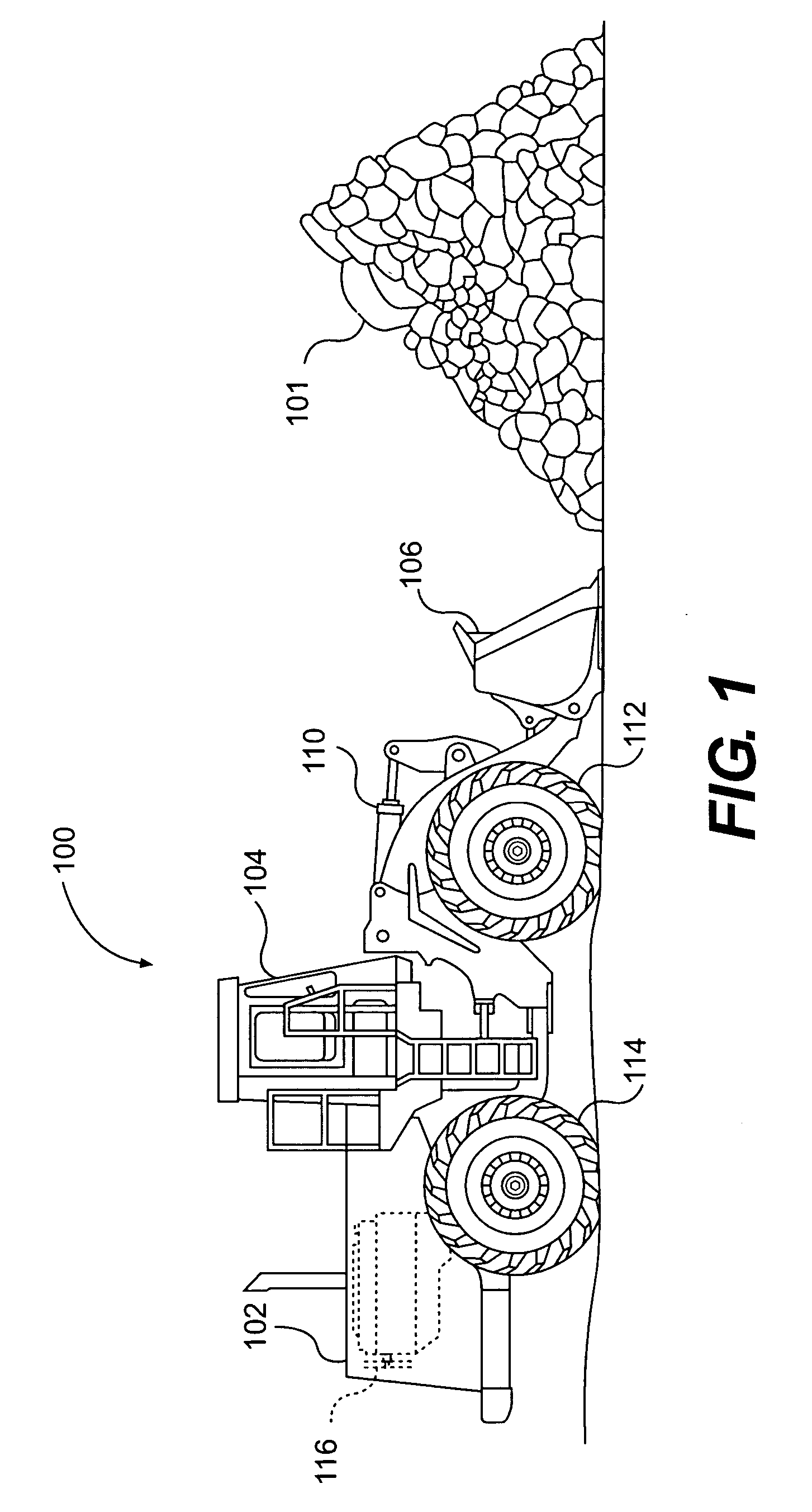
[0017] Referring to FIG. 1, a work machine 100 is illustrated approaching a pile of material 101. The work machine 100 may include an engine housing 102, an operator station 104, and a work implement 106, such as, for example, a bucket for digging and loading material. In the example of work machine 100 being a wheel loader, the work implement 106 is powered and controlled by a lift actuator 108 (shown in the block diagram of FIG. 2) and a tilt actuator 110. The lift and tilt actuators 108, 110 may be, for example, hydraulic fluid cylinder actuators. However, the lift and tilt actuators 108, 110 could be other actu...


PUM


Abstract

An automatic loading control system for loading a work implement of a work machine with material from a pile may include a lift sensor configured to monitor a lift actuator and communicate a lift signal. The system may also include a tilt sensor configured to monitor a tilt actuator and communicate a tilt signal. A speed sensor may be configured to communicate a speed signal indicative of a speed of the work machine. A control module may be configured to receive the lift signal, the tilt signal, and the speed signal and generate a signal to control a rim-pull based on at least one of a lift velocity of the lift actuator, a tilt velocity of the tilt actuator, and a work machine velocity to facilitate movement of the work implement through the pile.

Description

TECHNICAL FIELD [0001] This disclosure is directed to a digging and loading system and, more particularly, this disclosure is directed to an automatic digging and loading system for a work machine. BACKGROUND [0002] Some work machines are useful to repetitiously perform processes of digging and loading. For example, a work machine, such as a wheel loader, may repetitively load material into its bucket and dump the material into the bed of a truck. Often, the repetitious work cycle can become tedious to an operator and the operator may become fatigued. As the fatigue sets in, the operator may work less efficiently, thereby adversely impacting the efficiency of the work machine. [0003] To reduce operator fatigue and maintain a high level of machine productivity and efficiency, some work machines are equipped with controllers that automate portions of the repetitive work process. These controllers typically rely upon measured cylinder pressures and positions to determine when to implem...

Claims


Application Information

Patent Timeline
Patent Type & Authority Applications(United States)
IPC IPC(8): B66C23/00
CPCE02F9/2029E02F3/434
Inventor ALSHAER, BASSAM JAMEELINGRAM, RICHARD G.KRONE, JOHN JAMESBERRY, JEFFREY KENTHARRIS, JARED JAMES
Owner CATERPILLAR INC
Learn More