
Graph display device, graph display method and computer- readable medium recording control program

a graph and display device technology, applied in the field of graph display devices, can solve the problems of taking a lot of time and labor, troublesome operation, etc., and achieve the effect of simple chang

Active Publication Date: 2014-10-23
CASIO COMPUTER CO LTD
View PDF10 Cites 14 Cited by
  • Summary
  • Abstract
  • Description
  • Claims
  • Application Information

AI Technical Summary

Benefits of technology

This patent describes a new way to create and edit graphics on a computer screen that show how different values affect each other. It uses a special formula called a function, which allows users to easily see changes made through various user interfaces. Overall, this technology makes it easier than ever before to modify and analyze complex functions.

Problems solved by technology

The technical problem addressed in this patent is the difficulty and time-consuming process of changing the value or the change space of a coefficient in a functional expression using a graphing calculator. The present invention aims to provide a solution to this problem by displaying a graph corresponding to the change when the graph corresponding to the functional expression is displayed.

Method used


Image

  • Graph display device, graph display method and computer- readable medium recording control program
  • Graph display device, graph display method and computer- readable medium recording control program
  • Graph display device, graph display method and computer- readable medium recording control program

Examples


Embodiment Construction

[0023]Now, exemplary embodiments of the present invention will be described below by referring to the drawings.

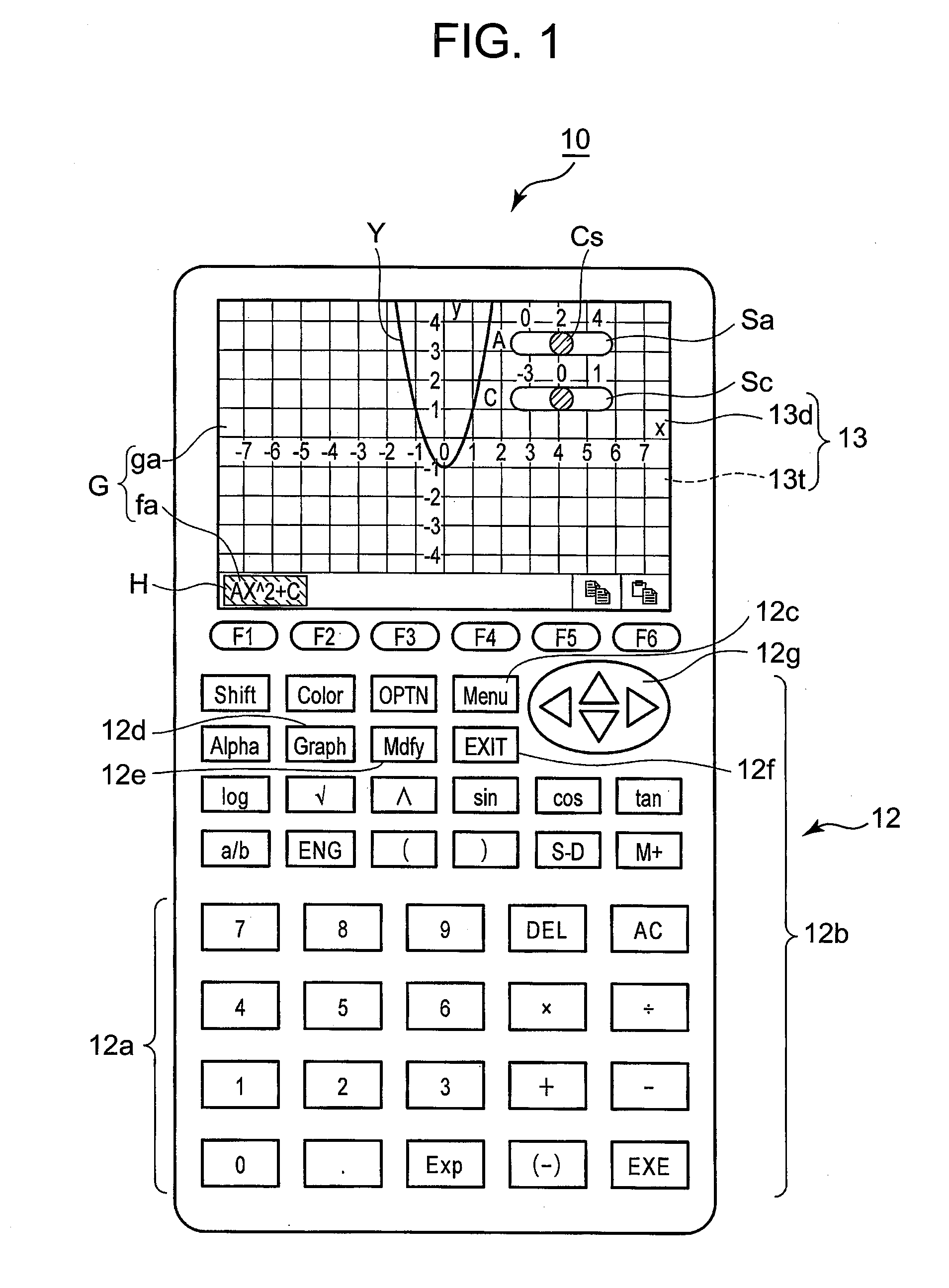
[0024]FIG. 1 is a front view showing a structure of an external appearance of a graphing calculator 10 according to an exemplary embodiment of a graph display device of the present invention.

[0025]The graph display device is formed as an exclusively used graphing calculator 10 which is described below or formed as a tablet terminal having a display function of a graph corresponding to a functional expression, a portable telephone, a portable game machine or the like.

[0026]The graphing calculator 10 has a function which displays an inputted functional expression and a graph corresponding to the functional expression.

[0027]In a main body of the graphing calculator 10, a key input part 12 is provided within a range as long as about two-thirds from a lower end of a front surface of the main body. A touch panel display part 13 is provided within a range as long as about one-thir...


PUM


Abstract

A graph display device includes an expression input unit, a graph display control unit, first and second display control units and a coefficient changed graph display control unit. The expression input unit recognizes a functional expression. The graph display control unit displays a graph corresponding to the recognized functional expression in a display part. The first display control unit displays a first user interface object for changing a numeric value set to a variable when a coefficient in the functional expression is the variable. The second display control unit displays a second user interface object for changing a numeric value as a constant when a coefficient in the functional expression is the constant. The coefficient changed graph display control unit displays a graph corresponding to the functional expression in which a numeric value changed by the first or second user interface object is set as a coefficient value.

Description


Claims


Application Information

Patent Timeline
Owner CASIO COMPUTER CO LTD
Learn More