
Apparatus for insertion in a tank and method thereof

a technology for insertion apparatus and tank, which is applied in the directions of special-purpose vessels, cleaning using liquids, transportation and packaging, etc., can solve the problems of reducing the durability and pressure rating of the hose, the chain structure is not strong enough to use for cleaning operations, and the cleaning power of these devices is reduced

Inactive Publication Date: 2015-01-01
STONEAGE
View PDF1 Cites 6 Cited by
  • Summary
  • Abstract
  • Description
  • Claims
  • Application Information

AI Technical Summary

Benefits of technology

The patent describes an apparatus for insertion in enclosed spaces, such as vessels, that can be easily positioned using a hose and actuator. The apparatus includes a tube with straight and curved portions, and a plurality of nested segments that can be extended and retracted to displace the tube. The apparatus can be easily fixed in position and can maintain alignment with the vessel's horizontal line while varying its vertical position. The technical effect of this invention is to provide a simple and effective way to position an apparatus in enclosed spaces.

Problems solved by technology

The cleaning power of these devices is lessened by the limited access available in the tank interior for these devices, for example, these devices can remain relatively distant from the ends of the tank.
The number of pipes or scissors sections, for example, usable with these devices, and hence the extent to which these devices can expand to reach all areas of the tank interior, is limited by the fact that the folded pipes and scissors sections must first fit through the limited space of the tank opening.
Further, to enable a hose to be folded or scissored, the hose must necessarily be relatively flexible, which reduces the durability and pressure rating of the hose.
However, the chain structure is not sturdy enough to use for cleaning operations.

Method used


Image

  • Apparatus for insertion in a tank and method thereof
  • Apparatus for insertion in a tank and method thereof
  • Apparatus for insertion in a tank and method thereof

Examples


Embodiment Construction

[0020]Furthermore, it is understood that this invention is not limited to the particular methodology, materials and modifications described and as such may, of course, vary. It is also understood that the terminology used herein is for the purpose of describing particular aspects only, and is not intended to limit the scope of the present invention, which is limited only by the appended claims.

[0021]Unless defined otherwise, all technical and scientific terms used herein have the same meaning as commonly understood to one of ordinary skill in the art to which this invention belongs. Although any methods, devices or materials similar or equivalent to those described herein can be used in the practice or testing of the invention, the preferred methods, devices, and materials are now described.

[0022]It should be understood that the use of “or” in the present application is with respect to a “non-exclusive” arrangement, unless stated otherwise. For example, when saying that “item x is A...


PUM


Abstract

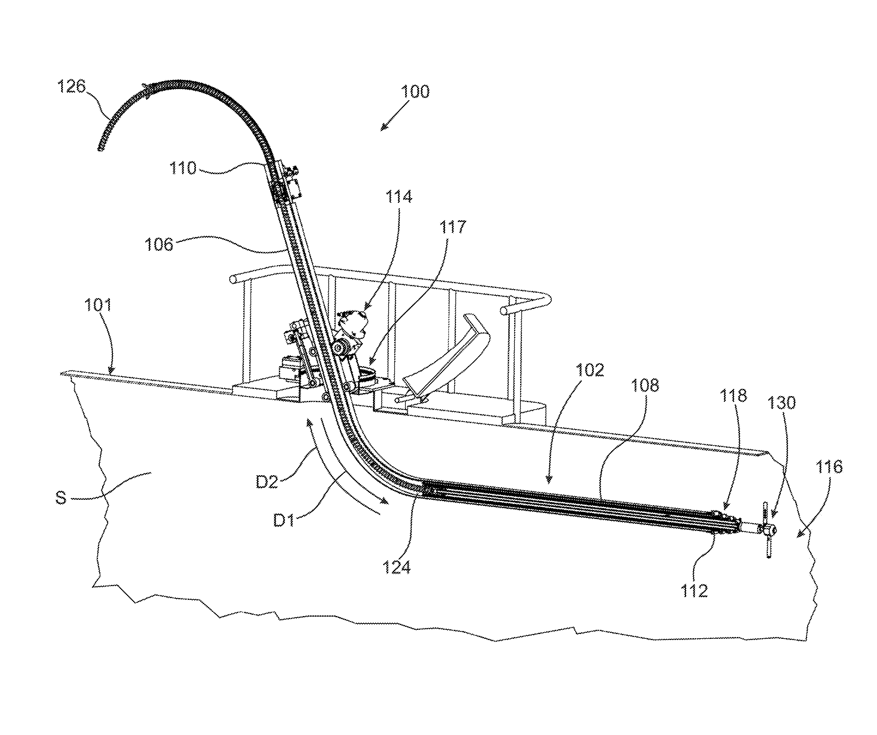
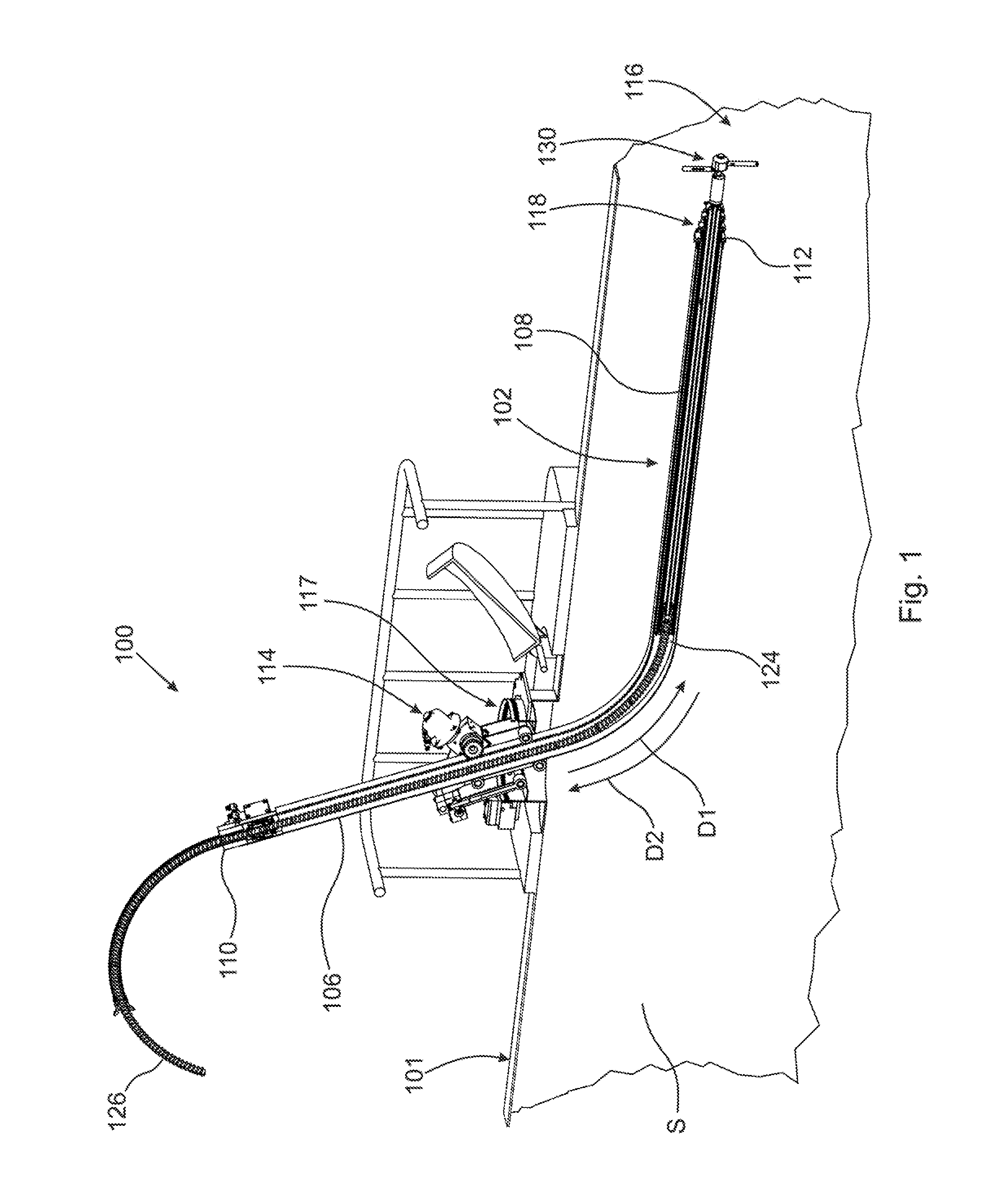
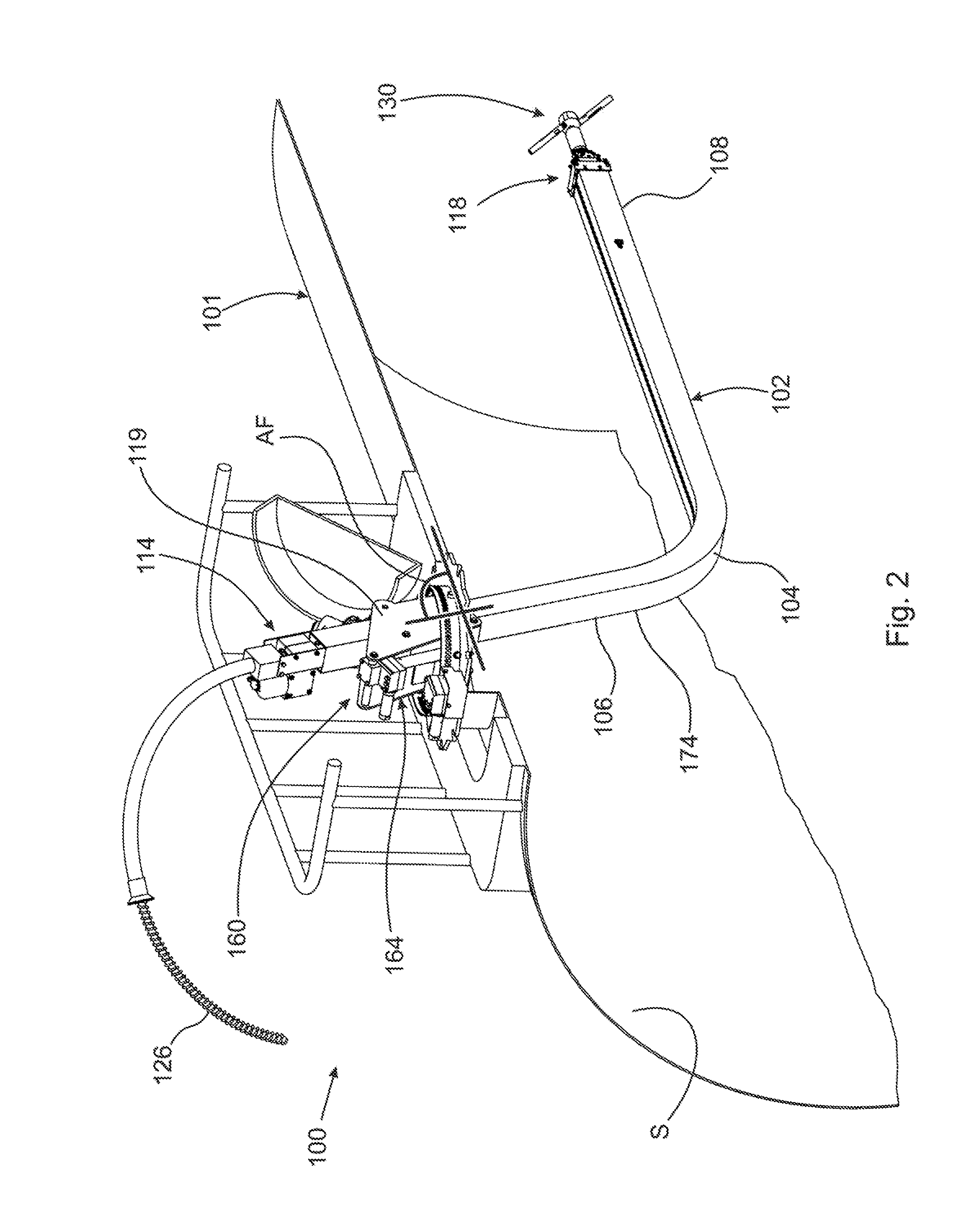
An apparatus for insertion in an enclosed space, including: a tube with: first and second substantially straight portions including first and second ends of the tube, respectively; and a curved portion connecting the first and second portions. The apparatus includes: a plurality of nested segments at least partially disposed within the first substantially straight portion of the tube and connected to the first substantially straight portion; and a first actuator engageable with the tube to displace the first and second substantially straight portions of the tube into and out of the enclosed space through an opening into the enclosed space. The tube is arranged to accept a hose passing through the tube, and a distal segment from the plurality of nested segments is connectable to the hose.

Description

CROSS REFERENCE TO RELATED APPLICATIONS[0001]This application is a division of U.S. patent application Ser. No. 13 / 078,634, filed Apr. 1, 2011, entitled APPARATUS FOR INSERTION IN A TANK AND METHOD THEREOF, the content of which is incorporated herein by reference in its entirety.FIELD OF THE INVENTION[0002]The present disclosure relates generally to an apparatus for insertion in a tank and a method for inserting an apparatus into an interior space of a tank. In particular, the present disclosure relates to an apparatus including a tube with a curved portion connecting straight portions, insertable through an opening in the tank. The tube can be used to convey high pressure fluids for cleaning the interior of the tank.BACKGROUND OF THE INVENTION[0003]It is known to insert various devices through an opening in a tank into an interior space of tank to clean an interior of the tank. One principle of operation associated with these devices is inserting a device through the opening in the...

Claims


Application Information

Patent Timeline
Patent Type & Authority Applications(United States)
IPC IPC(8): B08B9/093
CPCB08B9/093Y10T137/0419Y10T137/0402B08B9/043Y10T137/60B08B9/0813B63B57/02
Inventor ZINK, GERALD, P.
Owner STONEAGE
Learn More